Apparatus for cervical manipulation and methods of use

a cervical and apparatus technology, applied in the field of apparatus and methods for manipulating the female cervix, can solve the problems of discomfort or even harm to patients, undetected withdrawal of the distal balloon, and discomfort to patients, and achieve the effect of easy and intuitive operation

Inactive Publication Date: 2008-05-08
FEMSUITE
View PDF19 Cites 32 Cited by
  • Summary
  • Abstract
  • Description
  • Claims
  • Application Information

AI Technical Summary

Benefits of technology

[0011]In view of the foregoing, it is an object of the present invention to provide apparatus for manipulating the cervix that may be operated easily and intuitively by a clinician.

Problems solved by technology

The opposing pressures of the two balloons stabilize the cervix, but neither balloon is actually anchored to the cervix, Consequently, the two balloons must be manually adjusted in an attempt to properly seat the balloons against the internal and external ora, and application of excessive force on the proximal balloon may cause discomfort to the patient or an undesired withdrawal of the distal balloon even after inflation.
The disk in Zink is not anchored to the cervix and the balloon must be manually adjusted in an attempt to properly seat the device against the internal and external ora, a process that is cumbersome and that may involve one or more resettings of the proximal stop to securely engage the cervix.
Instead, the cervical blade in Mohajer requires skill to apply and may cause discomfort or even harm to the patient if improperly used.
Additionally, the shape of the inner catheter in Blaisdell does not protect the uterine walls against accidental perforations that may be caused by the catheter tip and body, and the occluding member in Blaisdell can be retained against the external os only by continuous pressure applied by the clinician, because the smooth conical walls of the occluding member provide no gripping action against the external os.

Method used


Image

  • Apparatus for cervical manipulation and methods of use
  • Apparatus for cervical manipulation and methods of use
  • Apparatus for cervical manipulation and methods of use

Examples


first embodiment

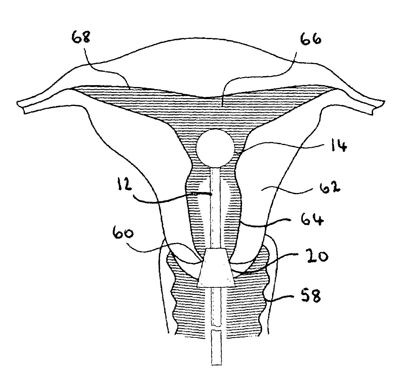
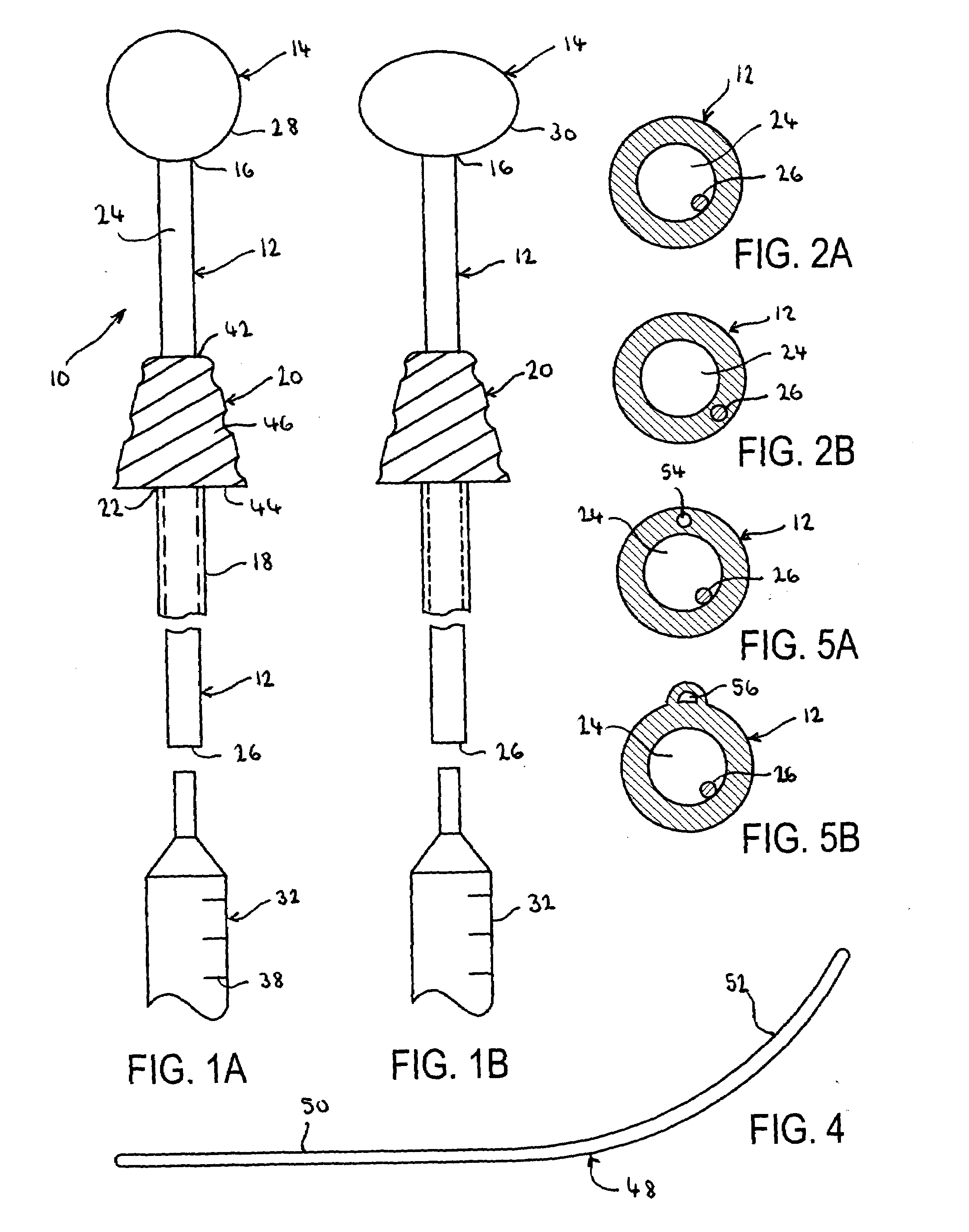
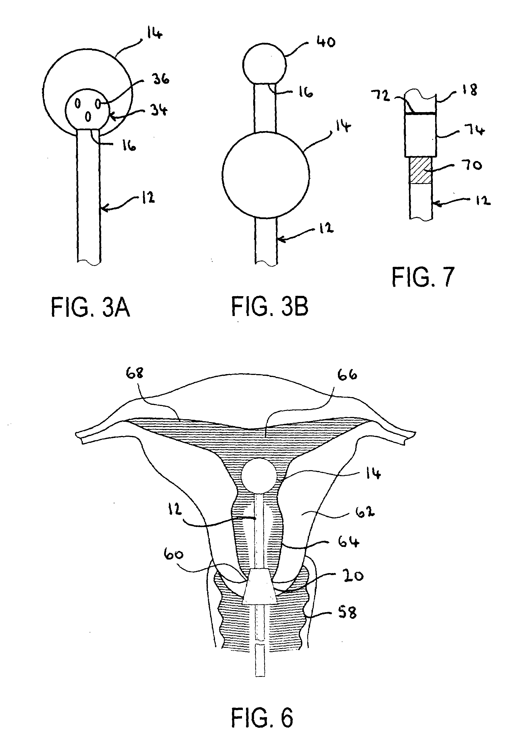
[0035]Referring first to FIGS. 1A-1B, an apparatus for cervical manipulation constructed in accordance with the principles of the present invention is described. In its most basic components, apparatus for cervical manipulation 10 includes inner tubular member 12, having inflatable balloon 14 disposed at distal end 16, and outer tubular member 18, having applicator member 20 disposed at distal end 22.

embodiment 10

[0036]Inner tubular member 12 is manufactured from a flexible or semi-rigid material, for example, from surgical-grade polypropylene. Lumen 24 extends longitudinally between distal end 16 and proximal end 26, and provides fluid communication between proximal end 26 and balloon 14. With further reference to FIGS. 2A-2B, flexible wire 26 is coupled to the wall of lumen 24, and is preferably attached to the wall of lumen 24, as shown in FIG. 2A, but in a variant of embodiment 10, flexible wire 26 may be embedded within the wall of lumen 24, as shown in FIG. 2B.

[0037]Within the context of the present specification, the term “flexible wire” is used to indicate a wire that bends under lateral pressure but that reacquires its original shape after lateral pressure is released. Such a flexible wire may be manufactured from a metallic material, for example, from steel, or from a non-metallic material, for example, from highly oriented polypropylene, or from a combination of metallic and non-m...

second embodiment

[0060]Referring now to FIG. 8, an apparatus for cervical manipulation constructed in accordance with the principles of the present invention is described. Apparatus 76 is structured in a manner similar to apparatus 10, and the same components will be identified hereinafter by the same reference numerals. The main difference between apparatus 10 and apparatus 76 consists in having balloon 14 and applicator member 78 both disposed on apparatus 76 on a single tubular member 80. More specifically, balloon 14 is disposed at distal end 82 of tubular member 80 and applicator member 78 is disposed proximally of balloon 14, along threaded portion 84.

[0061]Applicator member 78 includes an inner lumen 86 that extends longitudinally between minor base 88 and major base 90 and that carries a threaded pattern that matches the pattern of threaded portion 84. After tubular member 80 has been inserted through cervical canal 64 and into uterine cavity 66, balloon 14 is inflated and applicator member ...


PUM


Abstract

In one embodiment, an apparatus for cervical manipulation includes an inner tubular member manufactured from a bendable, semi-rigid material having an inflatable balloon disposed at the distal end and a flexible wire coupled to the wall of a lumen within the inner tubular member, and also includes an outer tubular member within which the inner tubular member reciprocates and which carries at the distal end an applicator member shaped to engage the external os of a cervix.

Description

FIELD OF THE INVENTION[0001]The present invention relates to apparatus and methods for manipulating the female cervix during a variety of gynecological procedures. More particularly, the present invention relates to apparatus and methods that provide opposing pressures on the female cervix by compressing a balloon against the internal os and by contemporaneously anchoring an applicator member to the external os.BACKGROUND OF THE INVENTION[0002]The uterine cervix is situated in the lower region of the uterus and not only connects the uterine cavity to the vagina, but also maintains the uterus in proper position within the pelvis due to a complex ligamentary structure named retinaculum uteri. The cervix of a female adult is typically four centimeters long, and in contrast to the uterine corpus, most of the cervix structure is formed by dense collagenous tissue containing a small amount of smooth muscle fibers.[0003]Gynecological and obstetrical procedures may require manipulation of t...

Claims


Application Information

Patent Timeline
Patent Type & Authority Applications(United States)
IPC IPC(8): A61B17/42
CPCA61B17/34A61B17/3421A61B17/4241A61B2017/3486A61B2017/349A61M2210/1425A61M25/04A61M25/10A61M2025/0006A61M2025/0037A61M2025/0213A61B2017/3492
Inventor FEUER, GERALDSANDERS, GERALD J.
Owner FEMSUITE
Why Eureka
Try Eureka