
Endoscopic Tissue Separator Surgical Device

a tissue separator and surgical device technology, applied in the field of surgical devices and procedures, can solve the problems of increasing the blood flow capacity of the arteries and the living tissue supplied by the arteries, becoming extremely invasive, and affecting the survival of patients, so as to achieve the effect of less potential damage to the underlying tissu

Inactive Publication Date: 2008-05-08
DEKA PROD LLP
View PDF59 Cites 3 Cited by
  • Summary
  • Abstract
  • Description
  • Claims
  • Application Information

AI Technical Summary

Benefits of technology

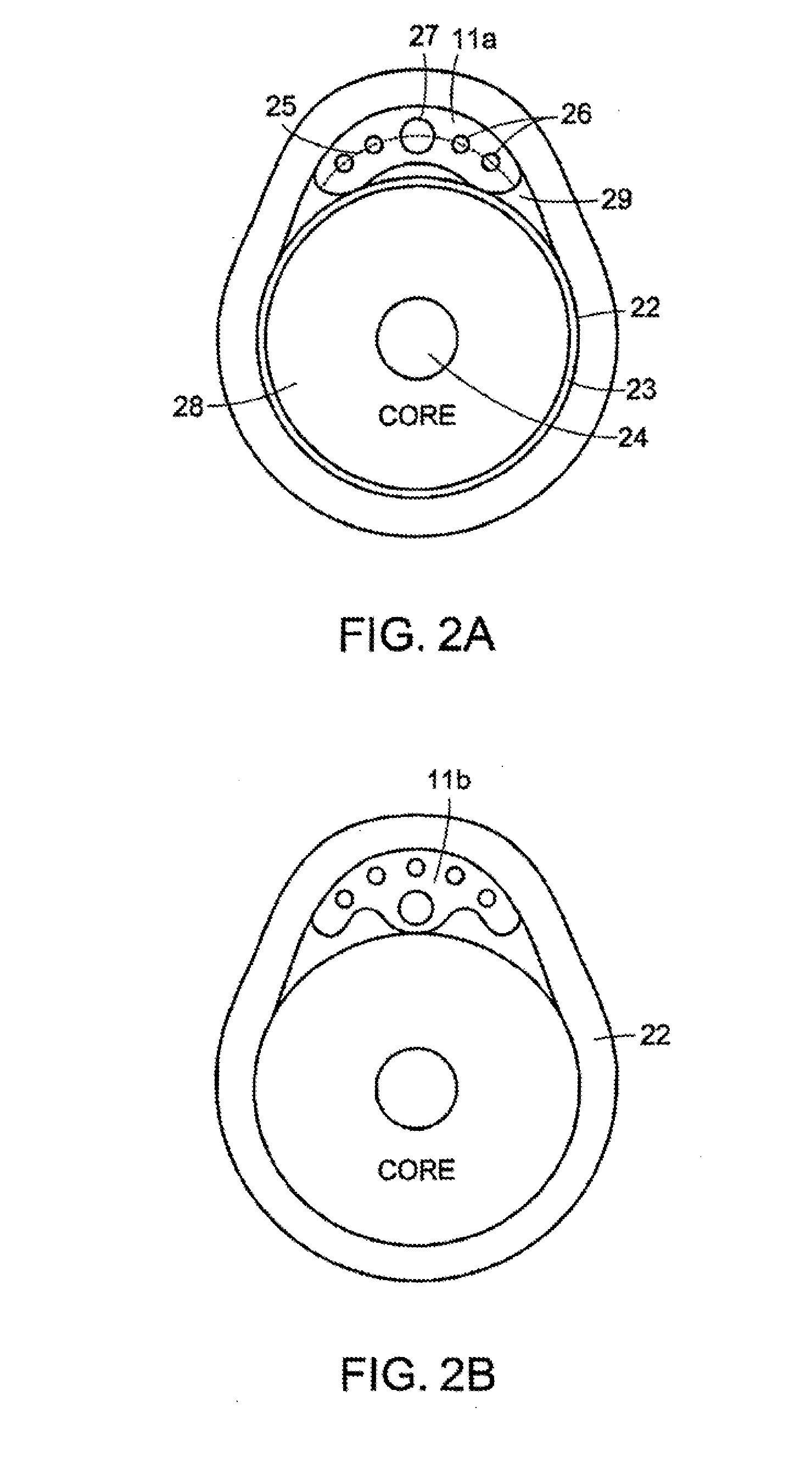
[0006] An improved endoscopic tissue separator surgical instrument is provided, that may advantageously cause less potential damage to the underlying tissue than provided by earlier technologies. In accordance with embodiments of the invention, a design for the spatula head, shaft, and switch is described, resulting in an endoscopic tissue separator instrument that, for example, can readily slide between the media and intima layer and the adventitia layer of a blocked artery, without excessive stretching of the adventitia layer.

Problems solved by technology

For example, excessive plaque build-up within arteries decreases the blood flow capacity of the arteries and of the living tissue supplied by the arteries.
Both procedures require incisions along the blockage and become extremely invasive for extensive blockages that may run the length from the groin to the knee, for example.
Although the catheter will remove sufficient blockage to restore normal flow, the procedure may not remove all the build-up, and there exists a risk that the catheter head may penetrate through the plaque build-up layer and damage the adventitia layer of the artery.
In addition, the procedure may worsen the blockage of the side branches by a “snowplow” effect as the catheter is pushed through the artery.
This increases the duration of the requisite operation and the risk of damage to the adventitia layer of the artery.

Method used


Image

  • Endoscopic Tissue Separator Surgical Device
  • Endoscopic Tissue Separator Surgical Device
  • Endoscopic Tissue Separator Surgical Device

Examples


Embodiment Construction

[0020] Definitions. As used in this description and the accompanying claims, the following terms shall have the meanings indicated, unless the context otherwise requires:

[0021] Arc means a continuous curve having no inflections, including, for example, curves such as portions of a French curve, a hyperbola, and those with a circular angle of curvature.

[0022] Arcuate line of curvature means a line of curvature in the form of an arc, as defined above.

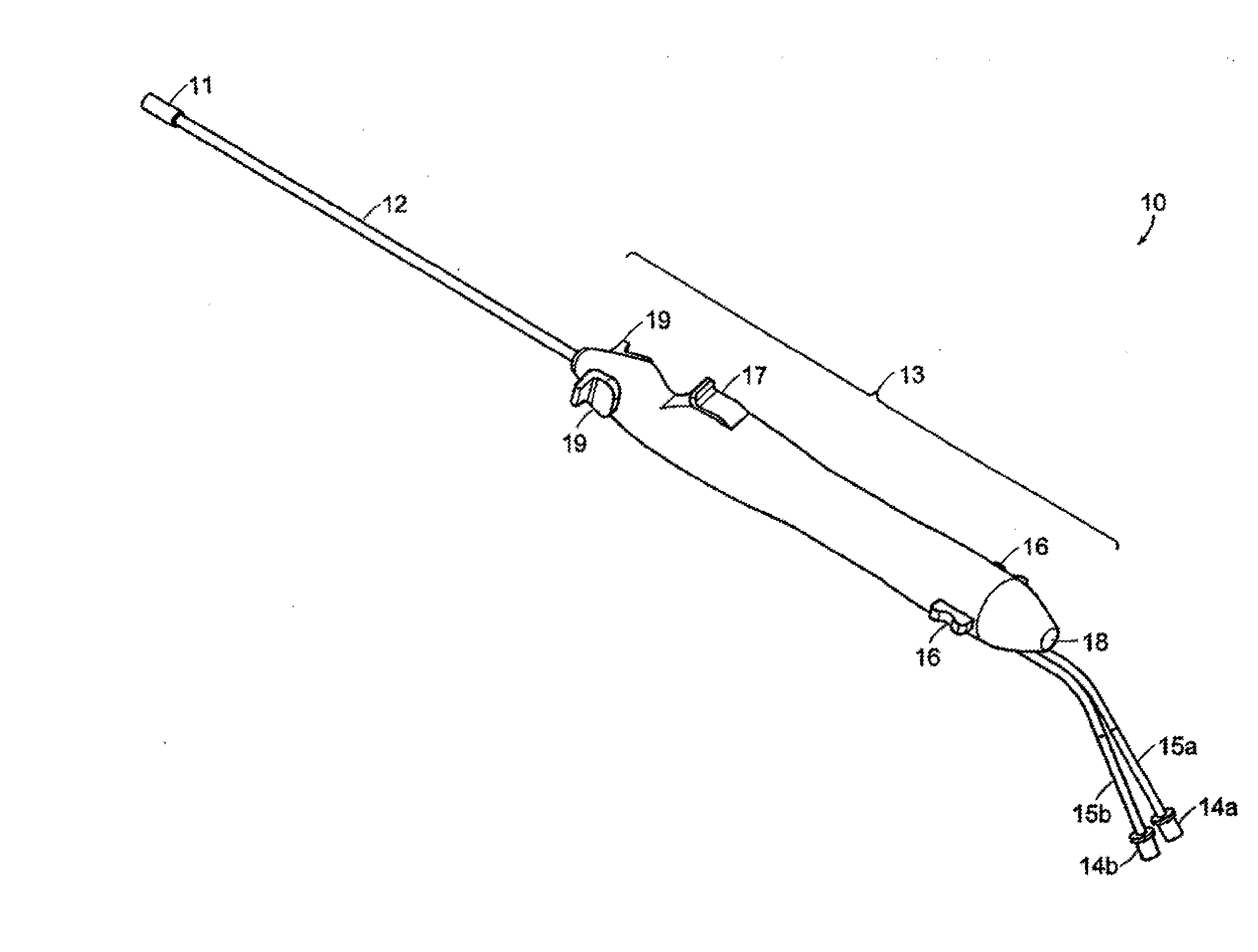
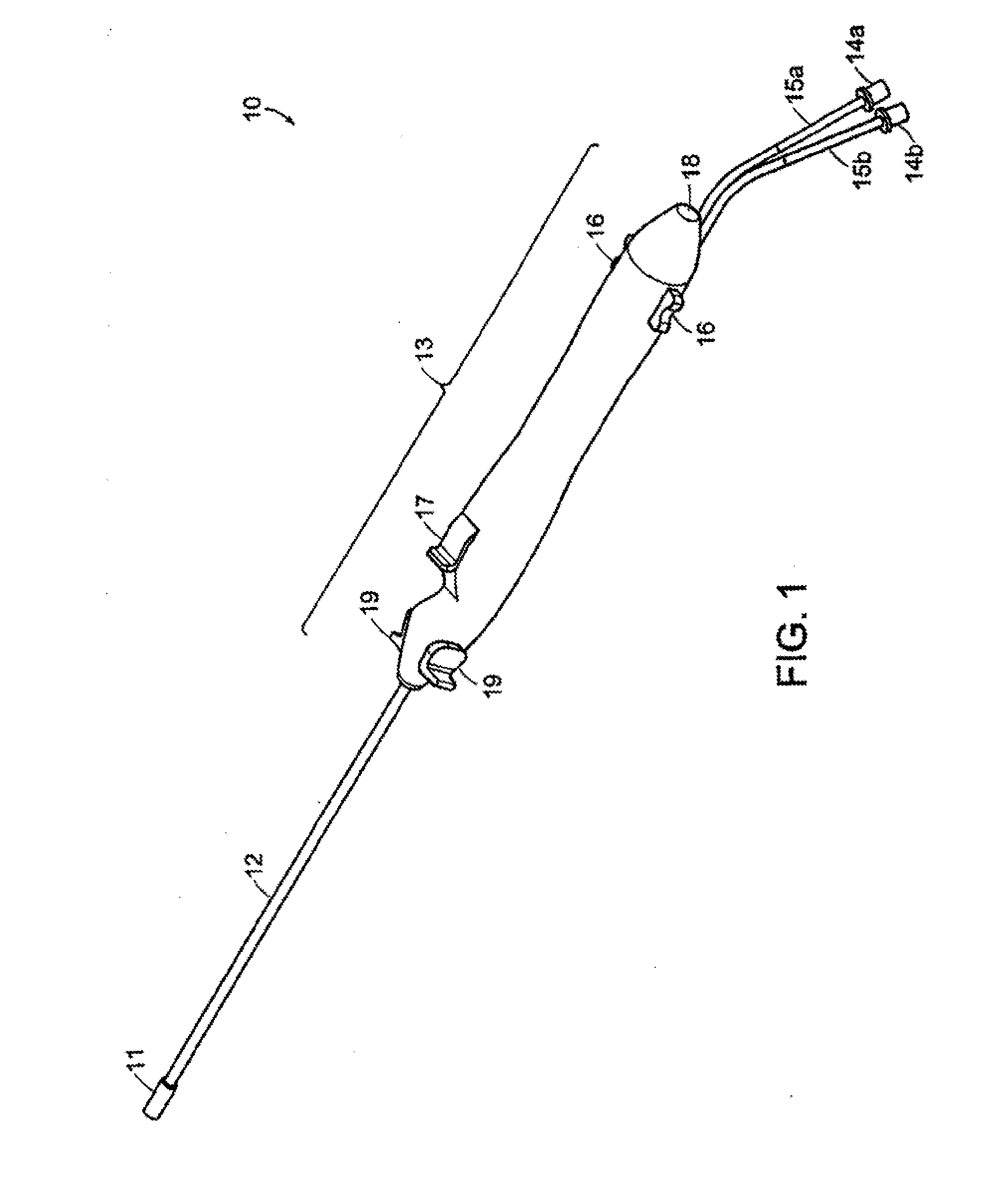
[0023]FIG. 1 shows a perspective view of an embodiment of the present invention. The tissue separator surgical instrument, generally designated by numeral 10 comprises a head 11, connected to a shaft 12, which in turn is connected to a handle 13. Handle 13 houses a first fluid port (not shown) that connects to a first fluid supply 15a with a female Leur connector 14a, and a second fluid port (not shown) connected to a second fluid supply line 15b with a female Leur connector 14b. A gas may be delivered to head 11 through supply line 15...


PUM


Abstract

An endoscopic tissue separator surgical device and method. The device has a multi-lumen shaft having proximal and distal ends, a central lumen for accepting an endoscope, and at least two fluid lumens, with a head coupled to the distal end of the shaft and a handle coupled to the proximal end. The head has an endoscope port and at least two fluid ports whose centers are all disposed along an arcuate line of curvature, while the handle has at least two fluid supply ports. Gas and fluid may be conveyed through the shaft from the handle to the head in the at least two fluid lumens separate from the lumen for accepting an endoscope. At least one lumen of the multi-lumen shaft may house a stainless steel tube with an inside diameter of sufficient size to accept an endoscope.

Description

CROSS REFERENCE TO RELATED APPLICATIONS [0001] This application is a divisional of co-pending U.S. application Ser. No. 10 / 161,094 filed on Jun. 3, 2002, herein incorporated by reference, which is a continuation-in-part of U.S. application Ser. No. 09 / 703,532, filed Nov. 1, 2000, which in turn claims priority from U.S. Provisional Application, Ser. No. 60 / 165,707 filed Nov. 16, 1999, both of which are incorporated herein by reference.TECHNICAL FIELD AND BACKGROUND ART [0002] The present invention relates to surgical devices and procedures, and more particularly to the separation and / or extraction of material during surgical procedures. [0003] For example, excessive plaque build-up within arteries decreases the blood flow capacity of the arteries and of the living tissue supplied by the arteries. Normal blood flow may be restored by either removing the plaque build-up or by bypassing the blocked section of the artery. Both procedures require incisions along the blockage and become ex...

Claims


Application Information

Patent Timeline
Patent Type & Authority Applications(United States)
IPC IPC(8): A61B17/22A61B1/015A61B1/12A61B1/313A61B17/00A61B19/00
CPCA61B1/015A61B1/12A61B1/3132A61B17/22A61B2017/320741A61B19/5212A61B19/5225A61B2017/00353A61B17/3207A61B90/361A61B90/37
Inventor GRANT, KEVIN LEEGRINNELL, CHARLES M.TRACEY, BRIAN DANIEL
Owner DEKA PROD LLP
Learn More