Composite Tubular Structure

Inactive Publication Date: 2008-05-15
NOBILEAU PHILIPPE CONSTANT
View PDF1 Cites 15 Cited by
  • Summary
  • Abstract
  • Description
  • Claims
  • Application Information

AI Technical Summary

Benefits of technology

[0015] Another advantage of the invention is that for a given resistance to collapse, it uses thin layers of steel, so that the metallic structure formed by the layers can easily be plastically folded with a small radius of curvature while maintaining a reasonable level of strain. This foldable easiness allows to construct a structure easily deployable in situ prior to hardening of the material filling the intermediate cavities between the layers.
[0016] A further advantage is the capability of the tubular structure to be instal

Problems solved by technology

New methods for installation of tubular structures in well have recently been introduced like mono-diameter/mono-bore casing systems but have reduced mechanical performances, mostly in collapse.
However, beyond a certain pipe diameter, the dimensions of the necessary spool to store the pipe become prohibitive, as well as the necessary equipment for its unwinding.
In well casing, the road size constraints and the requirements to locate big size spool on rigs make this solution less attractive if not impossible.
However, these two solutions have the dr

Method used


Image

  • Composite Tubular Structure
  • Composite Tubular Structure
  • Composite Tubular Structure

Examples


first embodiment

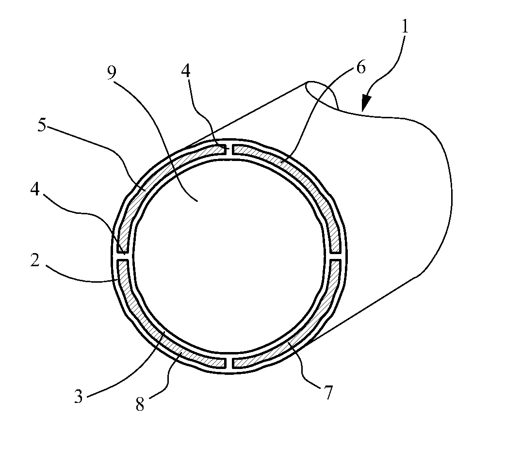
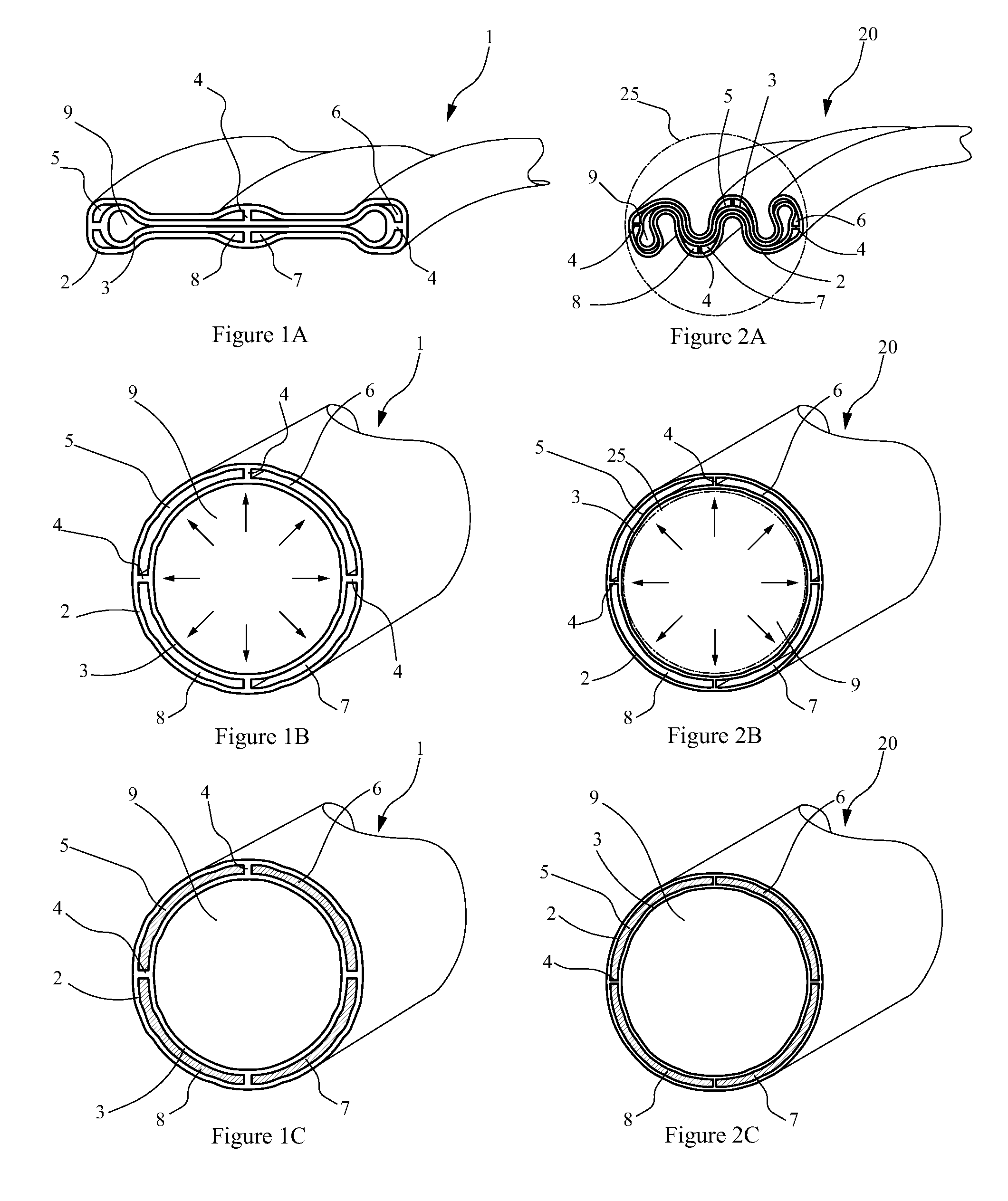
[0044] A first embodiment is represented in reference to FIGS. 1A, 1B and 1C. The installation of a structure, which could either be a pipeline / flowline or a downhole casing as in the present description, starts from a multi-layered structure 1 in a longitudinally flattened shape (FIG. 1A). The multi-layered structure 1 which will most often be metallic includes a wall composed of a internal layer 3 and a external layer 2 of identical thickness, each pressed against one another and linked up by four bulkheads 4. Under a longitudinal flattened shape, the section of the structure is optimized to minimize its folding inertia on one radial axis to be easily wound on a spool of small diameter.

[0045] The internal layer 2 isolates an internal volume 9 and along with the external layer 3 and the four bulkheads 4, isolate four intermediate cavities 5, 6, 7 and 8.

[0046] The volume 9 corresponds to the internal volume of the tubular structure while the intermediate cavities 5, 6, 7, 8 allow t...

second embodiment

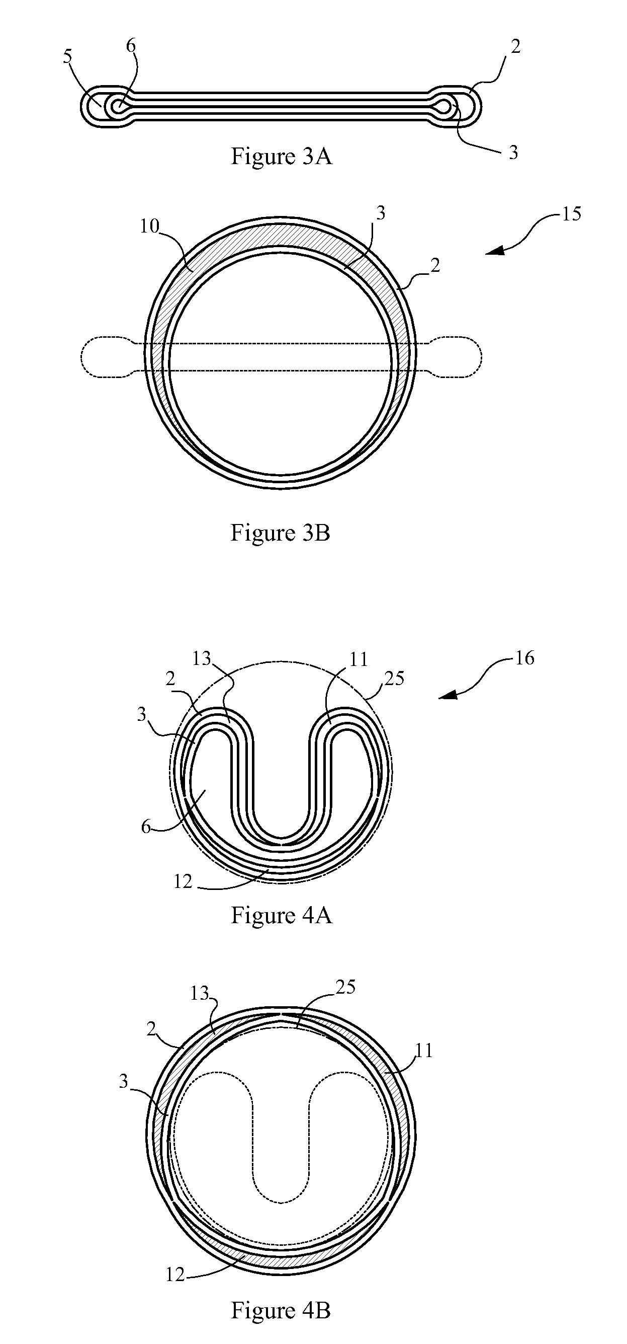
[0049] A second embodiment is represented referring to FIGS. 2A, 2B and 2C and illustrate the use of the principle of the invention as wellbore casing and particularly for mono-diameter casing. As before (FIG. 1A), the deployment of this tubular structure starts from a multi-layered metallic structure 20 in a somewhat longitudinally folded shape. The multi-layered metallic structure 20 includes a wall composed of an internal layer 3 and an outside layer 2 of identical thicknesses, each pressed against itself and linked up by four bulkheads 4.

[0050] Under its longitudinally crushed shape, the structure folding is optimized at the same time to minimize its bending inertia in one first axis to facilitate winding on spool of small dimension but also in order that the radial dimension perpendicular to the first axis is less than the diameter of a drift circle 25 in order to be able to lower it directly into a well having a passage with a drift circle 25. The volume 9 corresponds to the i...

third embodiment

[0055] A third embodiment is represented referring to FIGS. 5, 5A, 5B, 5C and 5D. The deployment starts from multi-layered metallic casing structure 30 in a longitudinally flattened shape. The multi-layered metallic structure 30 includes a wall composed of an internal layer 3 and an outside layer 2 of identical thicknesses, each pressed against itself and linked up by four bulkheads 4. Under a longitudinal flattened shape (FIG. 5A), the section of the structure is optimized to minimize its folding inertia to be easily wound on a spool of small diameter. It features a radial dimensions larger than the diameter of the drift circle 25.

[0056] After unwinding and straightened by rollers 19 and before being lowered into the well, the metallic structure 30 is deformed in the plastic range of the metal by mechanical action of rollers 16 and pebbles 17 which apply a lateral pressure directly over the structural layer 2 and indirectly over the structural layer 3 so that its radial dimensions ...


PUM


Abstract

Pipe-in-pipe composite tubular structure having between layers a hardenable filling material associating the layers to enhance the structure mechanical performance mostly in collapse. Prior to harden the filling material, the composite tubular structure can be longitudinally deployable between a folded configuration and a deployed configuration, and has a radial dimension increasing between the folded configuration and the deployed configuration. Such structure is well fitted to be used in oil-well downhole structure and casings or underwater pipeline/flowline.

Description

CROSS-REFERENCE TO RELATED APPLICATION [0001] This application is a continuation in part of application Ser. No. 10 / 416,773 filed Oct. 8, 2001 and a continuation in part of application PCT / IB2006 / 052738 filed Aug. 8, 2006 having a priority application FR0508438 filed Aug. 8, 2005. The entire disclosures of the prior applications are incorporated herein by this reference.TECHNICAL FIELD [0002] The present invention relates to well casing and oil transportation pipeline and in particular tubular structures requiring mechanical performances enhancement in-situ or after installation. BACKGROUND ART [0003] New methods for installation of tubular structures in well have recently been introduced like mono-diameter / mono-bore casing systems but have reduced mechanical performances, mostly in collapse. [0004] The patent application U.S. Ser. No. 10 / 416,772 of the applicant, offers a solution to improve the collapse resistance, but at the expense of substantial complications in the installatio...

Claims


Application Information

Patent Timeline
IPC IPC(8): E21B43/00E21B17/20E21B43/10E21B19/00
CPCE21B43/103F16L55/1656F16L11/20F16L11/12
Inventor NOBILEAU, PHILIPPE CONSTANT
Owner NOBILEAU PHILIPPE CONSTANT
Why Eureka
Try Eureka