
Composite Aircraft Structures With Hat Stiffeners

Active Publication Date: 2008-05-15
THE BOEING CO
View PDF11 Cites 140 Cited by
  • Summary
  • Abstract
  • Description
  • Claims
  • Application Information

AI Technical Summary

Benefits of technology

[0006]In accordance with the exemplary embodiments thereof described herein, the present invention provides a composite panel structure for an aircraft and methods for making it that overcome the above and other problems of the prior art, and that enable the thickness of the skins of the structures, such as the fuselage of a composite bodied aircraft, to be minimized while providing an acceptable levels of impact resistance and damage tolerance, thereby reducing both the weight and the cost of such structures.
[0010]In one preferred exemplary embodiment of the composite panel structure, the inner skin functions to carry substantially the entire design load of the structure, whereas, the outer skin functions as the aerodynamic surface of the aircraft, to provide impact resistance, e.g., to hail impact, and to protect the aircraft against lightning strikes.
[0014]Since the outer skin of the panel structure may be non-structural, in one advantageous embodiment, damage to the outer skin can be easily repaired by simply removing the damaged portion of the outer surface of the skin, e.g., with a saw, and cold-bonding a patch to the skin in place of the removed portion.

Problems solved by technology

However, prior art hat-stiffened structure concepts only allow for hat stiffeners extending in the fore-aft direction, and stiffeners extending in the other direction must be designed, fabricated, and assembled altogether differently.
As a result, extra weight, cost, manufacturing processes, and assembly time are added to the structure and overall production cost.
In case of a skin crack, the fail-safe chord provides an alternative load path for the hoop loads in the areas where the frame passes over the stringer, but is not as effective as it would be if tied directly to the skin.
In the current design, the frame load path is thus not optimal to insure the stringer continuity.

Method used


Image

  • Composite Aircraft Structures With Hat Stiffeners
  • Composite Aircraft Structures With Hat Stiffeners
  • Composite Aircraft Structures With Hat Stiffeners

Examples


Embodiment Construction

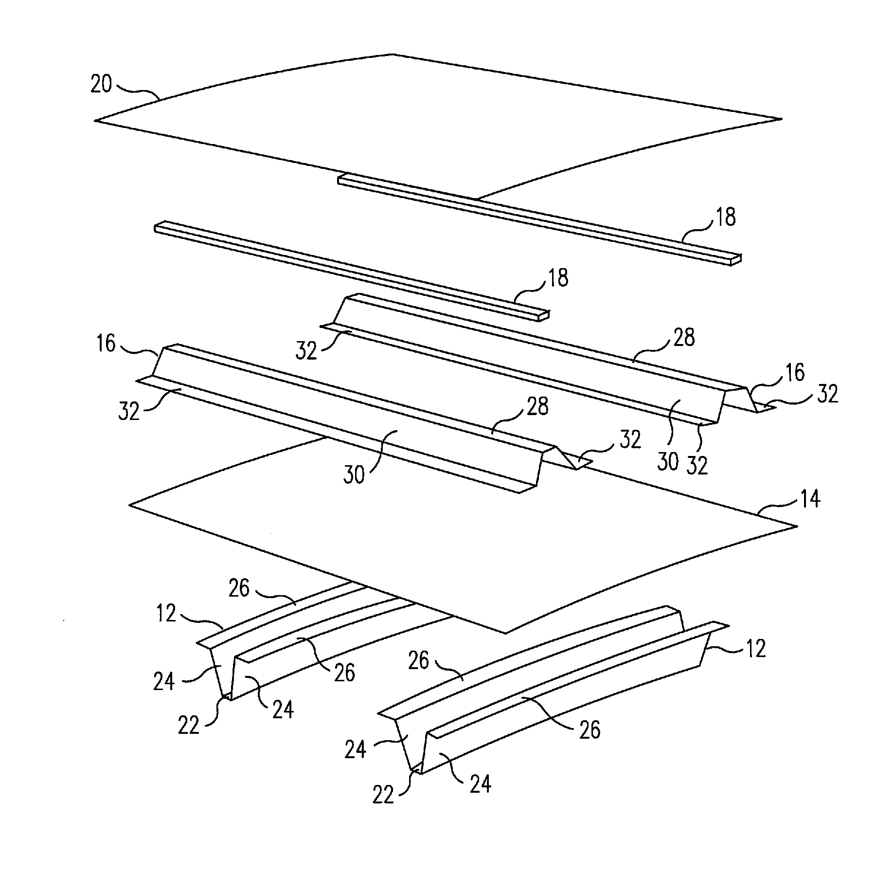
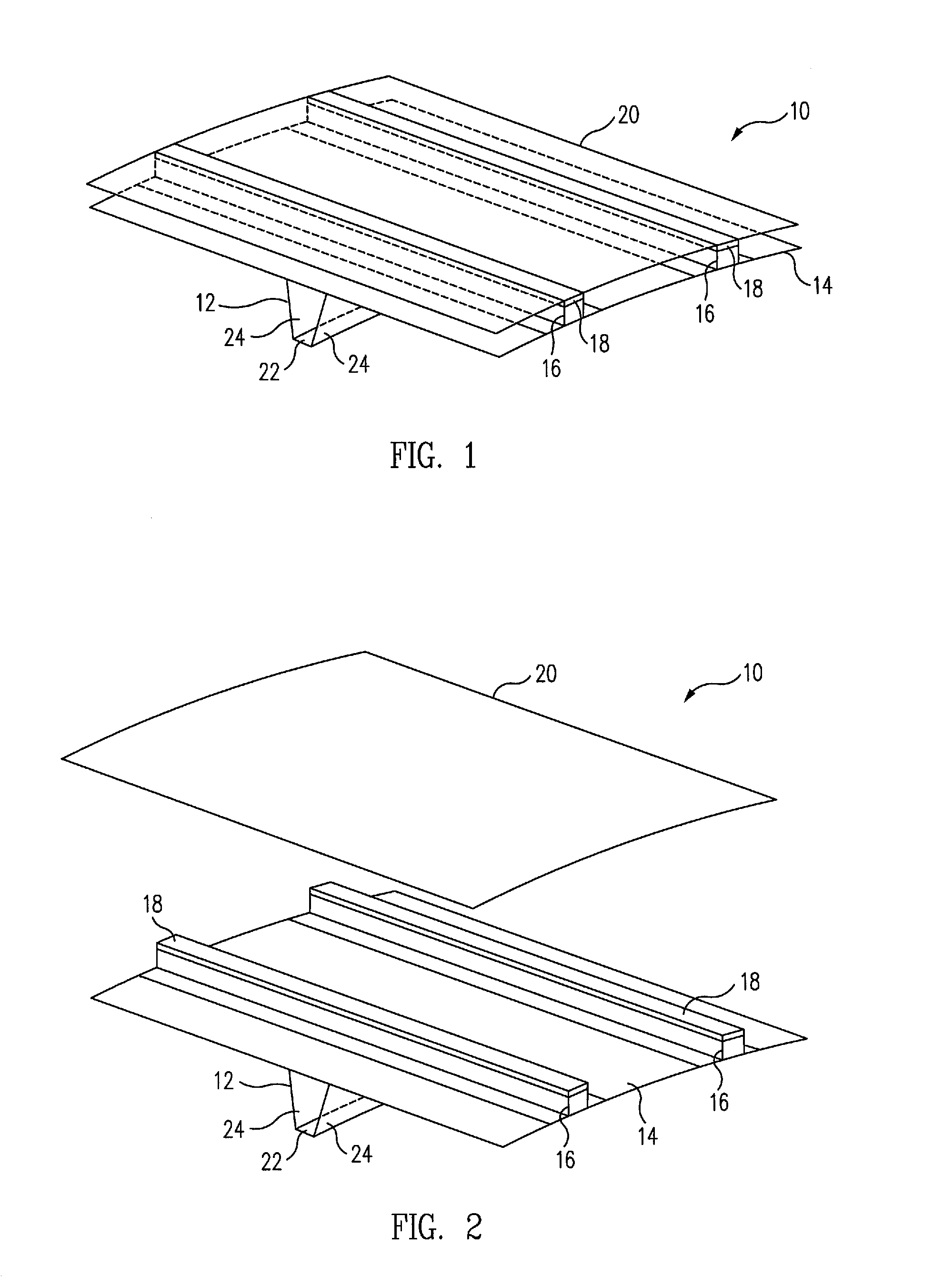
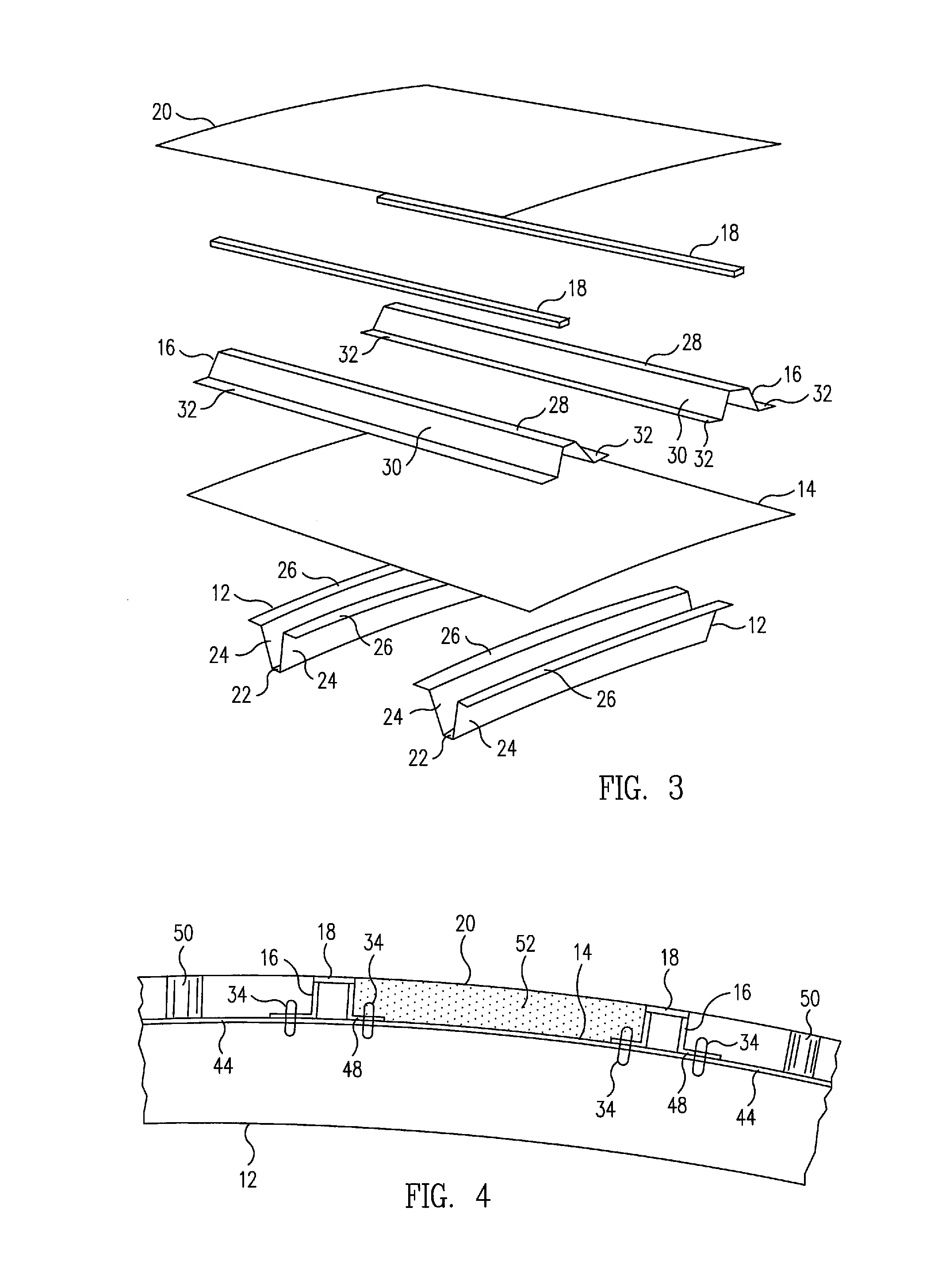
[0024]FIGS. 1-3 are unexploded, partially exploded and fully exploded upper front and side perspective view of a section of an exemplary embodiment of a composite panel structure 10 for aircraft in accordance with the present invention, respectively, and FIG. 4 is a cross-sectional end view of the panel structure section. Referring to FIGS. 1-4, the composite aircraft panel structure 10 comprises a plurality of annular frames 12 disposed coaxially along a long axis of the aircraft in a spaced, parallel relationship, each having a hat shaped cross section, an inner skin 14 having an inner surface bonded to an outer surface of the hat frames, a plurality of elongated stringers 16 disposed in a longitudinal direction along an outer surface of the inner skin in a spaced, parallel relationship, each also having a hat shaped cross section, an offset 18 bonded to an outer surface of each of the hat stringers, and an outer skin 20 having an inner surface bonded to an upper surface of each o...


PUM


Abstract

A composite panel structure for an aircraft includes a plurality of annular, hat-shaped frames disposed coaxially along a long axis of the aircraft in a spaced, parallel relationship, an inner skin having an inner surface bonded to an outer surface of the hat frames, a plurality of elongated, hat-shaped stringers disposed in a longitudinal direction along an outer surface of the inner skin in a spaced, parallel relationship, a solid or rigid foam offset bonded to an outer surface of each of the stringers, and an outer skin having an inner surface bonded to an upper surface of each of the offsets. The inner skin carries the loads of the structure and the outer skin defines an aerodynamic surface of the aircraft and provides impact and lighting protection. The frames, inner skin and stringers are formed on a single forming tool and cured and bonded with each other simultaneously.

Description

BACKGROUND[0001]The present disclosure relates to composite aircraft structures, such as fuselages, in general, and in particular, to composite aircraft structures incorporating closed hat stiffeners that enable the thickness of the skins of the structures to be minimized while providing acceptable levels of impact resistance and damage tolerance, thereby reducing the weight and cost of such structures.[0002]Composite aircraft structures offer many substantial advantages for the commercial aircraft industry. Several design considerations are critical to a successful and safely designed composite aircraft structure. Two of those design considerations, impact resistance and damage tolerance, are critical driving factors for weight and cost. Because of these two design requirements, composite fuselage skin structures may utilize a minimum gage that is much thicker than needed for carrying vehicle loads.[0003]In general, closed “hat” stiffeners provide great torsion rigidity, bending st...

Claims


Application Information

Patent Timeline
IPC IPC(8): B64C1/06B64D45/02
CPCB64C1/068Y02T50/433B64C2001/0072B64C1/12Y02T50/40
Inventor LEE, SHIN S.VIISOREANU, ADRIANKOCH, WILLIAM J.
Owner THE BOEING CO
Learn More