
Dual beam radar system

a radar system and beam technology, applied in the field of dual beam radar systems, can solve the problems of non-aircraft airborne objects such as birds, unable to respond to interrogation signals, and turning off transponders,

Active Publication Date: 2008-05-15
RAYTHEON CANADA LTD
View PDF46 Cites 113 Cited by
  • Summary
  • Abstract
  • Description
  • Claims
  • Application Information

AI Technical Summary

Benefits of technology

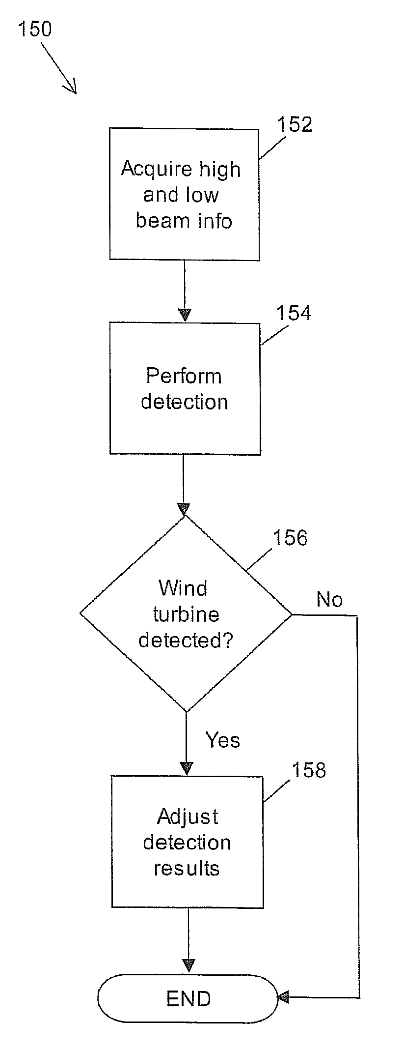
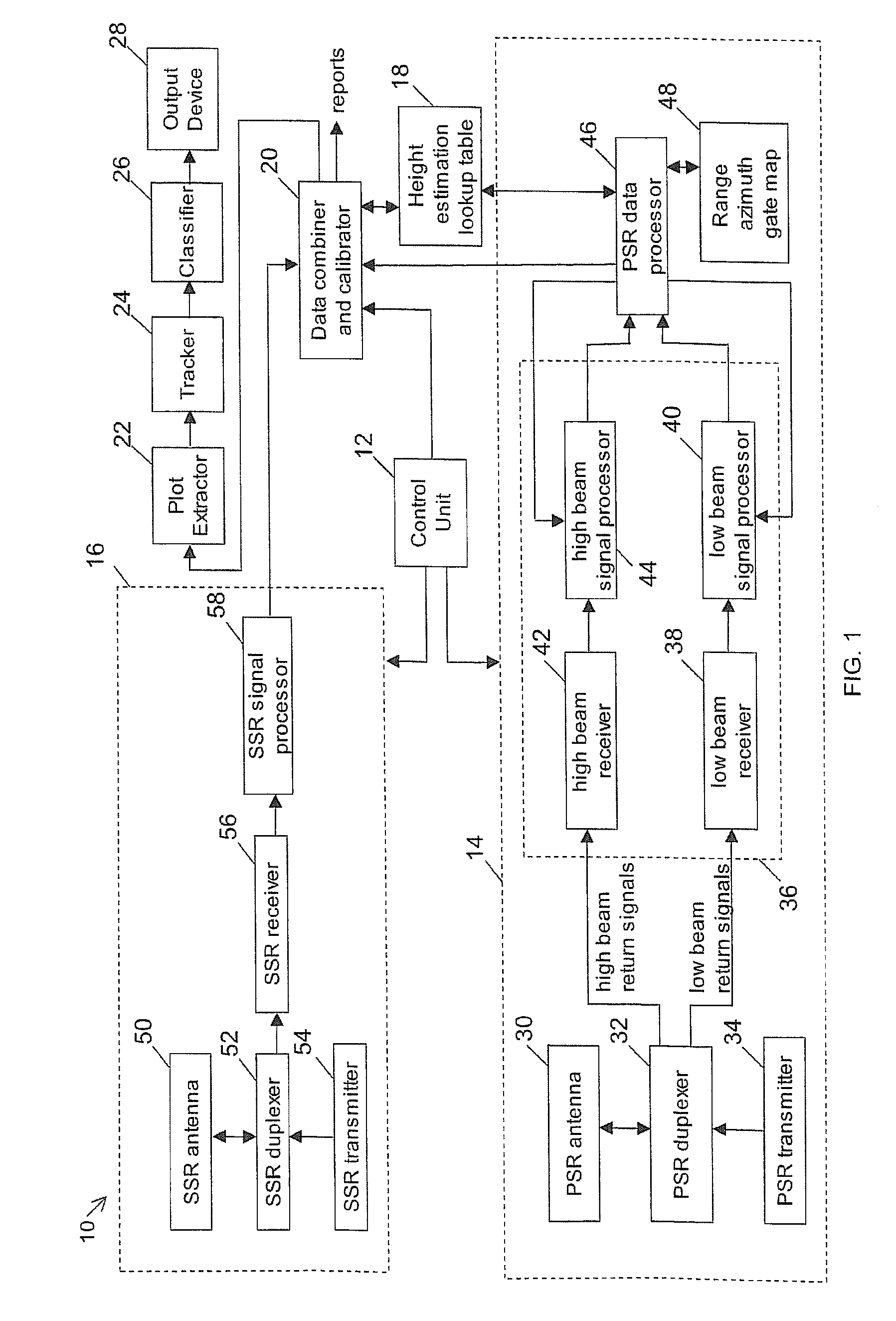
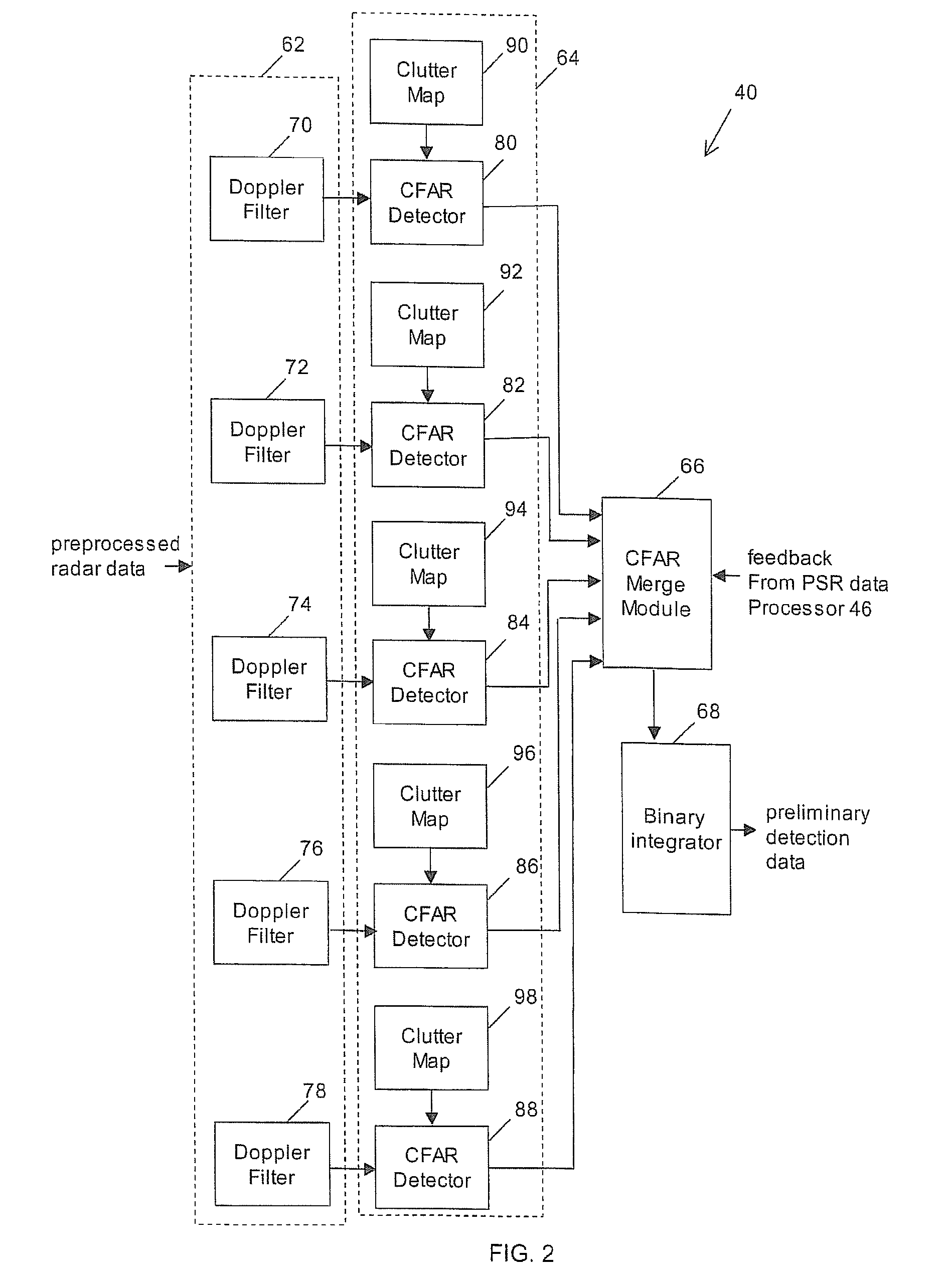
[0008]In accordance with the present invention, a method of processing radar data includes obtaining first and second sets of radar return signals concurrently, detecting targets in the first and second sets of radar return signals and identifying detected targets due to clutter. In one embodiment, first and second sets of radar return signals are concurrently obtained and an independent, concurrent low and high beam channel processing technique is used to provide a method of processing radar data to discriminate between airborne objects and clutter (e.g. wind turbines) in a surveillance area is provided. In one embodiment, a primary surveillance radar (PSR) locates and tracks objects within the surveillance area of the radar system by transmitting pulses along a low beam direction and concurrently using both a low beam and a high beam to receive radar return signals and concurrently processing return signals from objects in the surveillance area in high and low beam reception channels by beamforming each of the receiving beams to high and low directions. Such concurrent processing enables the technique to discriminate between airborne objects (e.g. aircraft) and clutter (e.g. wind turbines) in the surveillance area. In particular, in one embodiment, a data combiner and a calibrator can provide information on targets and clutter that are detected by at least one of the beams, by using data provided by the PSR, a height estimation lookup table, and in some cases a secondary surveillance radar.
[0010]In one embodiment, a primary surveillance radar (PSR) locates and tracks objects within the surveillance area of the radar system by transmitting a low beam and concurrently processing return signals from objects in the surveillance area in high and low beam reception channels by beamforming each of the receiving beams to high and low directions. The concurrent processing enables the radar system to discriminate between airborne objects and clutter in the surveillance area. More particularly, a data combiner and calibrator can provide information on targets and clutter that are detected by at least one of the beams, by using data provided by the PSR, the height estimation lookup table, and in some cases the SSR.

Problems solved by technology

However, some aircrafts, such as hijacked or enemy aircrafts, may deliberately turn off their transponders.
Other aircrafts may have a damaged transponder.
Furthermore, non-aircraft airborne objects, such as birds, cannot respond to the interrogation signals.
As a result conventional civil ATC radar systems cannot determine the height of these non-aircraft objects or aircrafts that do not respond to the SSR interrogation pulses, which can be a serious problem.
However, this has raised many concerns from ATC and military authorities since radar returns from wind turbines have the potential to distract and confuse air traffic controllers and can effectively mask genuine aircraft returns in the vicinity of the wind farm.
In fact, the presence of wind farms within the field of view of primary surveillance radars presents a considerable design challenge.
The overall effect of wind turbines are three fold: 1) the echoes (i.e. radar return signals) due to wind turbines may dominate and mask those originating from an aircraft resulting in a “radar blind zone” and missed detections, 2) the aircraft track may be seduced away from its correct path due to miss-association with an echo originating from a wind turbine, and 3) echoes originating from a wind farm may result in the generation of a high rate of false reports in the vicinity of the wind farm.

Method used


Image

  • Dual beam radar system
  • Dual beam radar system
  • Dual beam radar system

Examples


Embodiment Construction

[0020]It will be appreciated that for simplicity and clarity of illustration, where considered appropriate, reference numerals may be repeated among the figures to indicate corresponding or analogous elements or steps. In addition, numerous specific details are set forth in order to provide a thorough understanding of the exemplary embodiments described herein. However, it will be understood by those of ordinary skill in the art that the embodiments described herein may be practiced without these specific details. In other instances, well-known methods, procedures and components have not been described in detail since these are known to those skilled in the art. Furthermore, it should be noted that this description is not intended to limit the scope of the embodiments described herein, but rather as merely describing one or more exemplary implementations.

[0021]Generally, in an ATC radar system, tracks generated based on PSR data can be combined with tracks generated based on SSR dat...


PUM


Abstract

Various embodiments are described herein relating to a radar system and associated methods for detecting targets in the presence of certain types of clutter. The radar system generally comprises hardware operatively configured to obtain first and second sets of radar return signals concurrently, first circuitry operatively configured to detect targets in the first and second sets of radar return signals, and second circuitry operatively configured to identify detected targets due to clutter.

Description

CROSS REFERENCE TO RELATED APPLICATIONS[0001]This application claims the benefit under 35 U.S.C. §119(e) of Provisional application No. 60 / 857,784 filed Nov. 9, 2006 which application is incorporated herein by reference in its entirety.FIELD[0002]Embodiments are described herein for a dual beam radar system that can be used to discriminate between airborne targets and land-based clutter.BACKGROUND[0003]Generally, there are two types of radars that are used in a civil Air Traffic Control (ATC) radar system: a Primary Surveillance Radar (PSR) and a Secondary Surveillance Radar (SSR). The PSR transmits pulses and reports the range and azimuth of all detected objects in a given surveillance area. The detected objects include both aircraft and non-aircraft objects. The SSR transmits interrogation signals to aircrafts in the given surveillance area and receives information from the aircrafts that have operational transponders that respond to the interrogation signals. The information incl...

Claims


Application Information

Patent Timeline
Patent Type & Authority Applications(United States)
IPC IPC(8): G01S13/52
CPCG01S13/5246G01S13/913G01S13/872G01S13/726
Inventor HUBBARD, OLIVER HUGHWANG, JIAN
Owner RAYTHEON CANADA LTD
Learn More