Image forming apparatus and method thereof
a technology of image forming and forming apparatus, which is applied in the direction of digitally marking record carriers, visual presentation using printers, instruments, etc., can solve the problems of registration errors and cost rise, and achieve the effect of cost-effective and simple configuration
- Summary
- Abstract
- Description
- Claims
- Application Information
AI Technical Summary
Benefits of technology
Problems solved by technology
Method used
Image
Examples
first embodiment
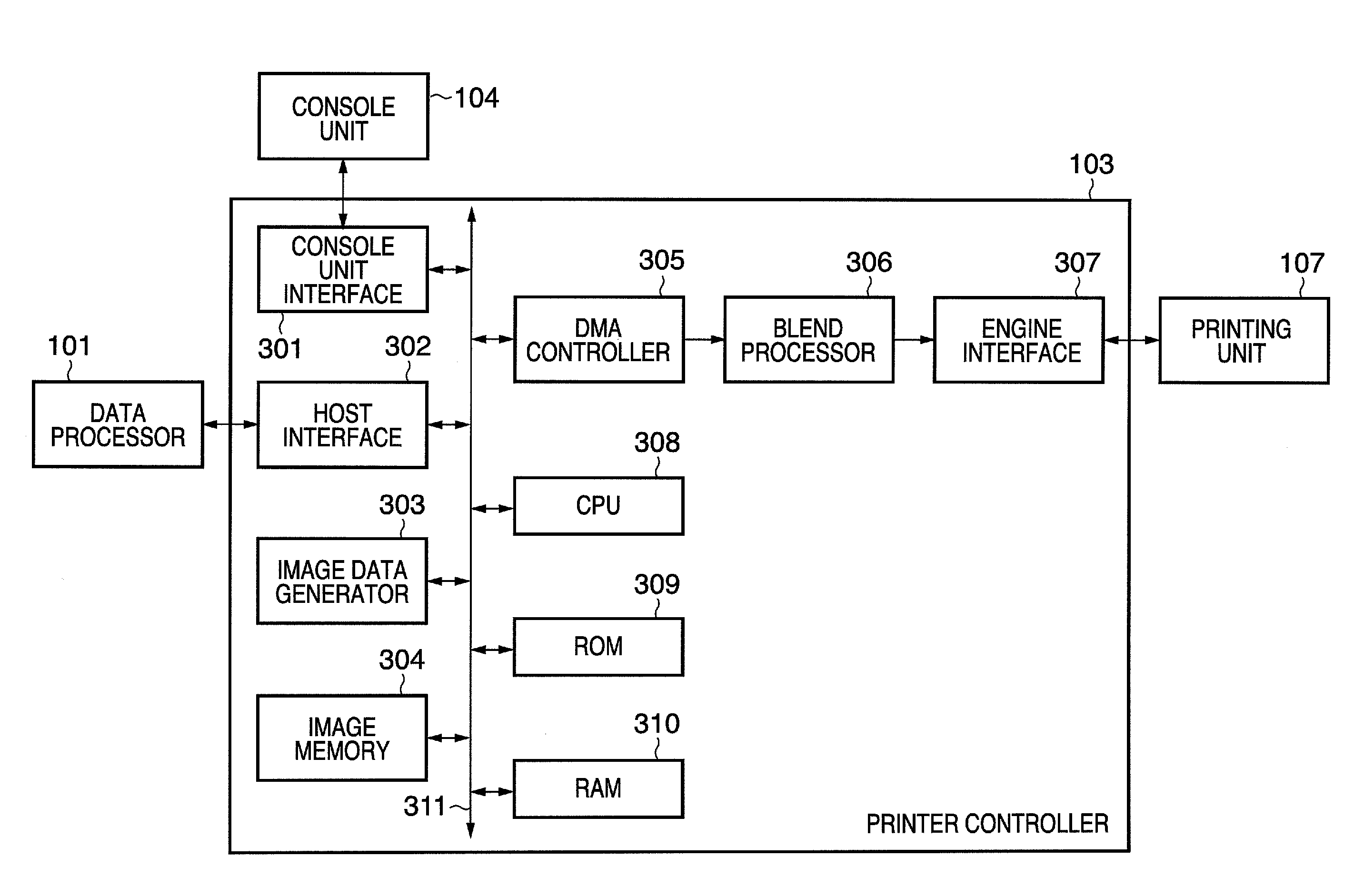
[0092]The operations of the DMA controller 305 according to a first embodiment of the present invention will be described next, with reference to FIGS. 6, 7A and 7B.
[0093]FIG. 6 depicts a view explaining a method of specifying scan line curve in the DMA controller 305 according to the first embodiment of the present invention. Note that here one line of bitmap image data is divided equally. Hereinafter, one portion of the divided line will be called a segment. Note that in the following description, the names representing segment lengths, the existence of line switches between adjacent segments, read data lengths for the blend processing around line switches, various addresses, and data lengths indicate the names of registers included in the register unit 501. As aforementioned, the CPU 308 instructs the DMA controller 305 to perform operations by writing values to these registers in the register unit 501.
[0094]A register RegSegLen for setting the length of the segments is provided ...
second embodiment
[0107]The operations of the DMA controller 305 according to a second embodiment will be described next, with reference to FIGS. 8 to 9B. Note that since the hardware configuration of the image processing apparatus according to this second embodiment is similar to the aforementioned first embodiment, description thereof will be omitted. The second embodiment differs from the first embodiment in that the segment length (RegSegLen) and blend length (RegOverlapLen) in one scan line are variable.
[0108]FIG. 8 depicts a view explaining a method of specifying scan line curve in a DMA controller according to a second embodiment of the present invention.
[0109]Here, registers RegSegLen[i] specifying the length (segment length) until switching positions on the line in accordance with the scan line curve are provided, since the segment length is variable. Further, a required number of registers RegUpDown[i] specifying whether to switch to the line above or below for each segment boundary are pro...
third embodiment
[0118]The operations of the DMA controller 305 according to a third embodiment of the present invention will be described next, with reference to FIGS. 10A, 10B, 11, 12A and 12B. Note that since the hardware configuration of the image processing apparatus according to the third embodiment is similar to the aforementioned first embodiment apart from the DMA controller 305, description thereof will be omitted.
[0119]FIG. 10A depicts a view explaining a method of specifying scan line curve in the DMA controller 305 according to the third embodiment of the present invention. Here, one line of bitmap image data is divided equally, similar to the first embodiment. The segment length (RegSegLen) is set in the register unit 501 of the DMA controller 305. Here, differently from the first embodiment, information (UpDown[i]) specifying not to switch lines between adjacent segments or to switch to the line above or below in accordance with an mount of the scan line curve is used. Here, the varia...
PUM
 Abstract
Description
Claims
Application Information
 - R&D
- Intellectual Property
- Life Sciences
- Materials
- Tech Scout
- Unparalleled Data Quality
- Higher Quality Content
- 60% Fewer Hallucinations
Browse by: Latest US Patents, China's latest patents, Technical Efficacy Thesaurus, Application Domain, Technology Topic, Popular Technical Reports.
© 2025 PatSnap. All rights reserved.Legal|Privacy policy|Modern Slavery Act Transparency Statement|Sitemap|About US| Contact US: help@patsnap.com


