Lighting assemblies and components for lighting assemblies

a technology for lighting assemblies and components, applied in the field of lighting assemblies, can solve the problems of reducing the life of lamps and compromising performance, and achieve the effect of increasing the surface area and mass of the assembly and heat dissipation

Active Publication Date: 2008-05-15
IDEAL IND LIGHTING LLC
View PDF83 Cites 407 Cited by
  • Summary
  • Abstract
  • Description
  • Claims
  • Application Information

AI Technical Summary

Benefits of technology

[0037]The lighting assemblies of the present inventive subject matter include unique heat dissipation structure extending from the tri

Problems solved by technology

Conversely, the dissipation of heat from LEDs and other solid state light emitters within a recessed downlight is very critical.
For insta

Method used


Image

  • Lighting assemblies and components for lighting assemblies
  • Lighting assemblies and components for lighting assemblies
  • Lighting assemblies and components for lighting assemblies

Examples


first embodiment

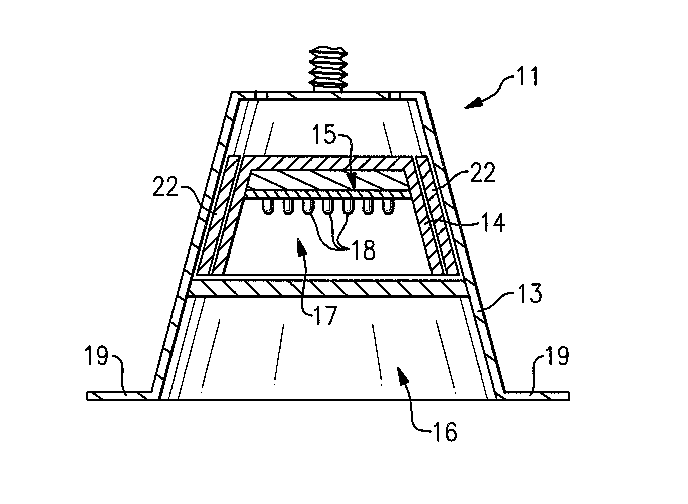
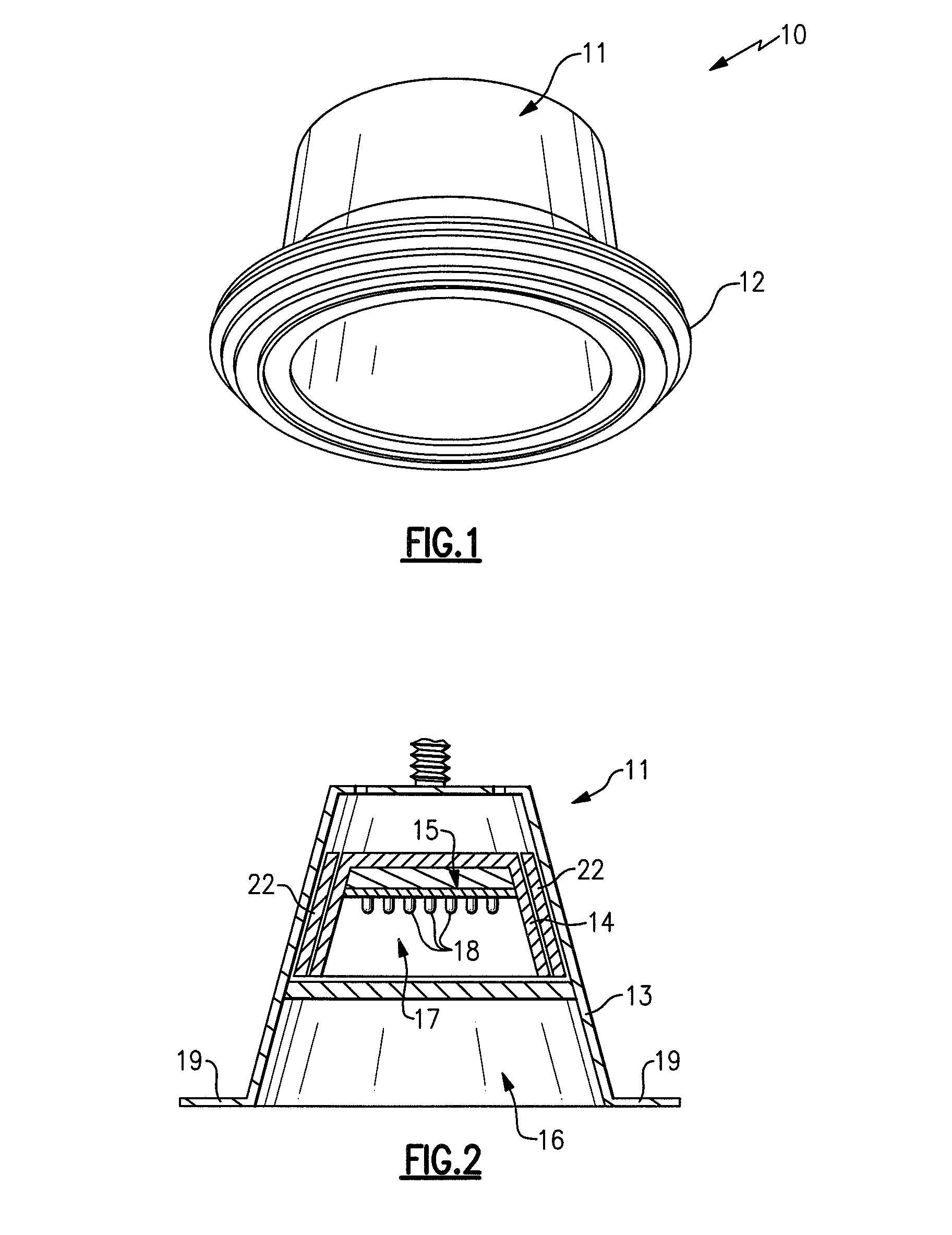
[0156]FIGS. 1-4 depict a lighting assembly in accordance with the present inventive subject matter. Referring to FIG. 1, there is shown a lighting assembly 10 which comprises a light engine assembly 11 and a room-side element 12 in contact with a portion of the light engine assembly 11. Referring to FIG. 2, the light engine assembly 11 comprises a trim element 13, a light engine housing 14 and a light engine 15. The trim element 13 defines a trim element internal space 16. The light engine housing 14 is positioned within the trim element internal space 16. The light engine housing 14 defines a light engine housing internal space 17. The light engine 15 is positioned within the light engine housing internal space 17 (and therefore is also within the trim element internal space 16) and comprises a plurality of LEDs 18. A thermal interface element 22 is positioned between the light engine housing 14 and the trim element 13

[0157]The trim element 13 comprises a flange portion 19 which ex...

second embodiment

[0163]FIGS. 7-9 depict a lighting assembly in accordance with the present inventive subject matter. Referring to FIG. 7, there is shown a lighting assembly 70 which comprises a light engine assembly 71 and a room-side element 72. Referring to FIG. 8, the light engine assembly 71 comprises a trim element 73 which comprises a flange portion 74.

[0164]FIG. 9 is a sectional view of the room-side element 72, and it shows the arrangement of the heat dissipating fins 75. As shown in FIG. 9, the room-side element 72 comprises an annular region 76 and the heat dissipating fins 75. As shown in FIG. 9, the heat dissipating fins extend away from the annular region 76 such that any planar section which includes an axis of the trim element 73 (e.g., the section shown in FIG. 9) extends through the heat dissipating fins 75, and within any of such planar sections, the heat dissipating fins 75 extend radially from the annular region 76 and define different angles relative to a plane which is perpendi...

third embodiment

[0165]FIG. 10 is a sectional view of a portion of a lighting assembly in accordance with the present inventive subject matter. Referring to FIG. 10, there is shown a lighting assembly 100 which comprises a light engine assembly 101 and a room-side element 102. The light engine assembly 101 comprises a trim element 103 which comprises a flange portion 104. The room-side element 102 comprises a first heat dissipating fin 105 which extends from the trim element 103 in a direction substantially parallel to an axis of the trim element 103, and four other heat dissipating fins 106 which extend such that any planar section which includes an axis of the trim element 103 (e.g., the section depicted in FIG. 10) extends through the heat dissipating fins 105, 106, and within any of such planar sections, the heat dissipating fins 106 are substantially parallel with each other.


PUM


Abstract

A lighting assembly, comprising a light engine assembly and a room-side element. The room-side element is in contact with the light engine assembly. The light engine assembly comprises at least one trim element and a light engine. The trim element defines a trim element internal space. The light engine comprises at least one solid state light emitter, and is positioned within the trim element internal space. Also, a lighting assembly, comprising a light engine assembly and means for dissipating heat from the light engine assembly.

Description

CROSS-REFERENCE TO RELATED APPLICATIONS[0001]This application claims the benefit of U.S. Provisional Patent Application No. 60 / 859,013, filed Nov. 14, 2006, the entirety of which is incorporated herein by reference.FIELD OF THE INVENTION(S)[0002]The present inventive subject matter relates to lighting assemblies for use in lighting devices, and lighting devices which include such light engine assemblies. In some embodiments, the present inventive subject matter relates to lighting assemblies and lighting devices which include solid state light emitters, for example, light emitting diodes.BACKGROUND OF THE INVENTION(S)[0003]A large proportion (some estimates are as high as twenty-five percent) of the electricity generated in the United States each year goes to lighting. Accordingly, there is an ongoing need to provide lighting which is more energy-efficient. It is well-known that incandescent light bulbs are very energy-inefficient light sources—about ninety percent of the electricit...

Claims


Application Information

Patent Timeline
IPC IPC(8): F21S8/04
CPCF21S8/02F21S48/328F21V29/004F21W2131/401F21V29/767F21Y2105/001F21V29/74F21V29/745F21V29/75F21Y2101/02F21Y2105/10F21Y2115/10F21S45/48F21V23/023Y10S362/80F21S45/47
Inventor TROTT, GARY DAVIDPICKARD, PAUL KENNETH
Owner IDEAL IND LIGHTING LLC
Why Eureka
Try Eureka