Backlight Unit and Display Apparatus Having the Same

a backlight unit and display device technology, applied in lighting and heating devices, lighting device details, instruments, etc., can solve the problems of reducing visibility, difficult to enhance only the visibility of the display screen as viewed obliquely sideways while lowering visibility, and directly front side, so as to reduce thickness, weight and cost, and facilitate switching

Inactive Publication Date: 2008-05-15
CITIZEN ELECTRONICS CO LTD
View PDF8 Cites 52 Cited by
  • Summary
  • Abstract
  • Description
  • Claims
  • Application Information

AI Technical Summary

Benefits of technology

[0016]In the backlight unit of the present invention, the elongated prisms of the first prism sheet and the elongated prisms of the second prism sheet may be at a predetermined angle to each other in plan view. In this case, it is possible to obtain directivity in which light is polarized in a direction perpendicular to the prisms on the first prism sheet. For example, if the ridges of the prisms on the second prism sheet extend vertically, the ridges of the prisms on the first prism sheet are arranged to extend parallel to a direction perpendicular to the ridges of the prisms on the second prism sheet, i.e. horizontally, whereby it is possible to obtain directivity in which light is polarized vertically.
[0017]In addition, the present invention provides a display apparatus including an image display panel and the above-described backlight unit of the present invention that is disposed at the back of the image display panel. The display apparatus further includes a switching control unit that performs on / off switching of the first light source to emit light and that also performs on / off switching of the second light source to emit light. In this display apparatus, it is possible to readily switch between the above-described directivities by arbitrarily switching between the on / off operations of the first and second light sources with the switching control unit.
[0018]In the display apparatus, the switching control unit may be arranged to be capable of controlling the amounts of light from the first light source and the second light source, respectively. Light from the second light source passes through two lightguide plates and two prism sheets. Therefore, when reaching the light exit surface, the light from the second light source has been attenuated more than light from the first light source. In this display apparatus, the luminance of exiting light can be kept constant before and after switching between the first and second light sources by setting the amount of light from the second light source is larger than that from the first light source. When the first light source and the second light source are turned on simultaneously, the amounts of light emitted therefrom can be controlled so that the luminance is similar to that when only either of them is turned on.
[0019]Further, the display apparatus of the present invention is characterized in that the image display panel is a liquid crystal display panel. That is, this display apparatus is a liquid crystal display apparatus using a liquid crystal display panel. Therefore, the apparatus can be reduced in thickness, weight and cost, and directional-characteristics switchable liquid crystal display can be obtained.
[0020]The display apparatus may be used in a car navigation system or an on-board television system. The use of the display apparatus in such a system enables selection of light directivity corresponding to each of the driver's seat, the passenger's seat and the back seat. Accordingly, bright and satisfactory visibility can be obtained at any of these seats.
[0021]In the display apparatus of the present invention, the image display panel may be adapted to be capable of displaying different images for a plurality of predetermined directions for viewing the display screen of the image display panel. That is, the display apparatus enables different images to be seen with satisfactory visibility in the respective directions for viewing the display screen of the image display panel.

Problems solved by technology

The above-described conventional backlight unit, however, still has the following problems to be solved.
Hence, the display screen can be viewed over a wide angle range, but it is difficult to enhance only visibility of the display screen as viewed obliquely sideways while lowering visibility thereof as seen from the directly front side.
Accordingly, the above-described conventional backlight unit is unsuitable for use in such car navigation systems.

Method used


Image

  • Backlight Unit and Display Apparatus Having the Same
  • Backlight Unit and Display Apparatus Having the Same
  • Backlight Unit and Display Apparatus Having the Same

Examples


first embodiment

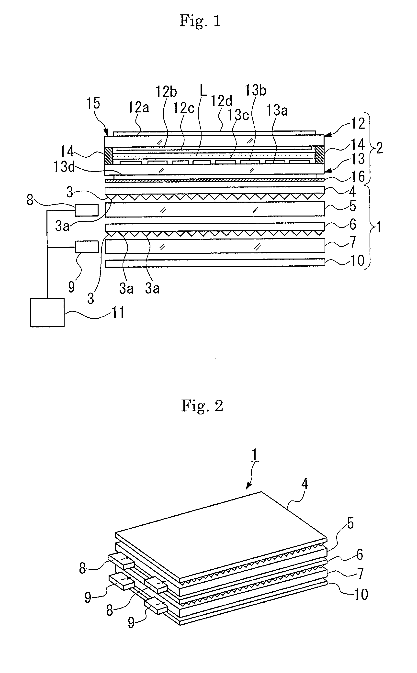
[0028]a backlight unit and display apparatus having the same according to the present invention will be described below with reference to FIGS. 1 to 5.

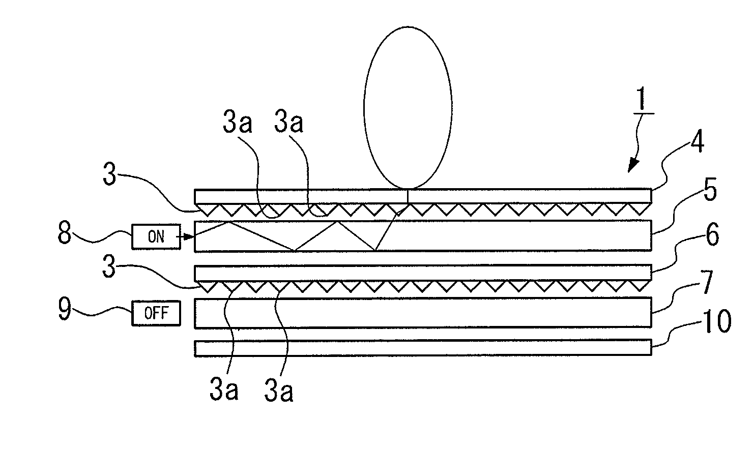
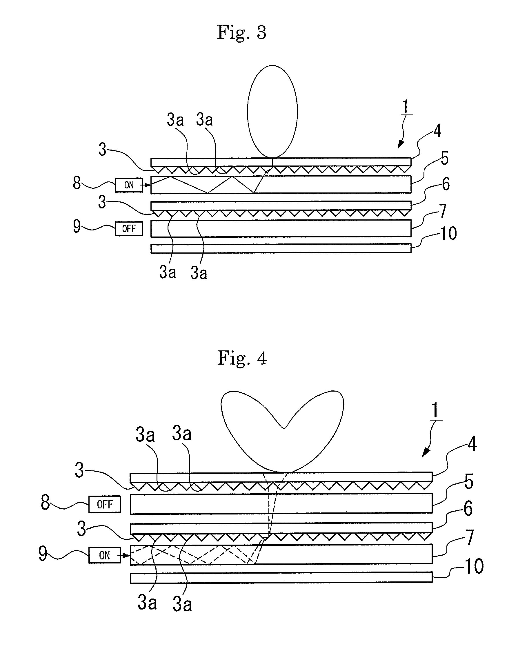
[0029]A backlight unit 1 in this embodiment has, as shown in FIGS. 1 and 2, a first prism sheet 4, a first lightguide plate 5, a second prism sheet 6, a second lightguide plate 7, a first light source 8, a second light source 9, and a reflective sheet 10. The first prism sheet 4 has an upper surface positioned adjacent to the back of a liquid crystal display panel (image display panel) 2 and a lower surface having mutually parallel elongated prisms 3 of triangular cross-section. The first lightguide plate 5 is disposed underneath the first prism sheet 4. The second prism sheet 6 is disposed underneath the first lightguide plate 5 and has a lower surface having mutually parallel elongated prisms 3 of triangular cross-section. The second lightguide plate 7 is disposed underneath the second prism sheet 6. The first light source 8 is disp...

second embodiment

[0056]Accordingly, in the second embodiment, the prisms 3 of the first prism sheet 4 provide directivity in two vertically oblique directions (as viewed in FIG. 6). Directivity in any directions can be obtained by adopting an arrangement in which the first prism sheet 4 is arbitrarily rotatable relative to the second prism sheet 6.

[0057]Although some embodiments of the present invention have been described above, the present invention is not necessarily limited to the foregoing embodiments but can be modified in a variety of ways without departing from the scope of the present invention.

[0058]For example, although in the foregoing embodiments the optical axis of light from each linear light source intersects the prisms 3 of the associated prism sheet perpendicularly, i.e. at an angle of 90°, the optical axis need not necessarily intersect the prisms 3 at right angles.

[0059]Although it is preferable to use white LEDs as the first light source 8 and the second light source 9, as has b...


PUM


Abstract

A backlight unit can change the directional characteristics of exiting light by selectively turning on two light sources. The backlight unit includes a first prism sheet (4) having on a lower surface thereof a plurality of parallel prisms (3), a first lightguide plate (5) disposed underneath the first prism sheet (4), a second prism sheet (6) disposed underneath the first lightguide plate (5) and having on a lower surface thereof a plurality of parallel prisms (3), a second lightguide plate (7) disposed underneath the second prism sheet (6), a first light source (8) disposed adjacent to an edge surface of the first lightguide plate (5) to emit light into the first lightguide plate (5), and a second light source (9) disposed adjacent to an edge surface of the second lightguide plate (7) to emit light into the second lightguide plate (7).

Description

[0001]This application claims priority under 35 U.S.C. § 119 to Japanese Patent application No. JP 2006-308604 filed on Nov. 15, 2006, the entire contents of which are hereby incorporated by reference.TECHNICAL FIELD[0002]The present invention relates to a backlight unit of a display apparatus for suitable use in car navigation systems, for example, and also relates to a display apparatus having the backlight unit.RELATED CONVENTIONAL ART[0003]Liquid crystal display apparatus for image display have been widely used in car navigation systems, on-board liquid crystal television systems, displays of personal computers, mobile phones, personal digital assistants (PDAs), etc. These liquid crystal display apparatus employ a backlight unit that applies illuminating light to a liquid crystal display panel from the back thereof to enhance the luminance of the display screen.[0004]Recently, there has been a demand that liquid crystal display apparatus allow an arbitrary choice between visibil...

Claims


Application Information

Patent Timeline
Patent Type & Authority Applications(United States)
IPC IPC(8): F21V7/04
CPCG02B6/0068G02F2001/133626G02B6/0076G02F1/133626
Inventor KATSUMATA, TOSHINOBUMIYASHITA, JUNJI
Owner CITIZEN ELECTRONICS CO LTD
Why Eureka
Try Eureka