Wireless communication network and method of dynamic channel selection of a wireless communication network

Inactive Publication Date: 2008-05-15
EATON CORP
View PDF13 Cites 153 Cited by
  • Summary
  • Abstract
  • Description
  • Claims
  • Application Information

AI Technical Summary

Benefits of technology

[0017]The method may further comprise employing as the function of background noise level or message traffic the selection of one of the different second wireless communication channels that has the lowest rolling average receive signal strength indicator value.
[0018]The method may determine whether more t

Problems solved by technology

During radio frequency communication between a network coordinator and one or more network devices, commun

Method used


Image

  • Wireless communication network and method of dynamic channel selection of a wireless communication network
  • Wireless communication network and method of dynamic channel selection of a wireless communication network
  • Wireless communication network and method of dynamic channel selection of a wireless communication network

Examples


Example

EXAMPLE 1

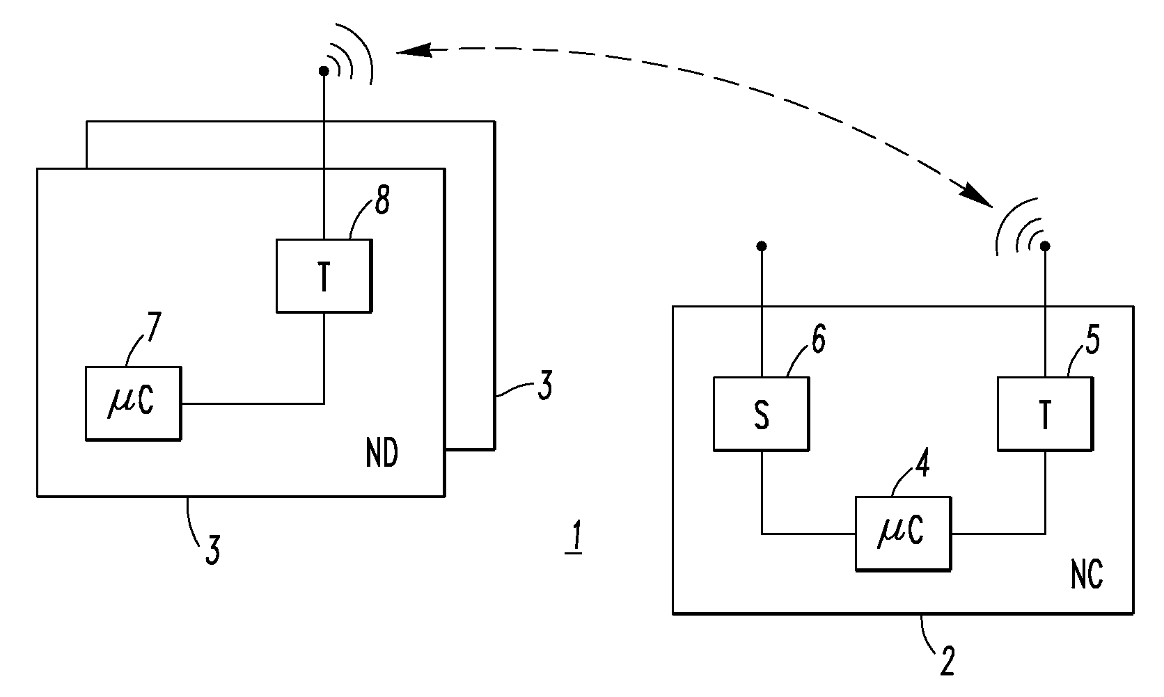
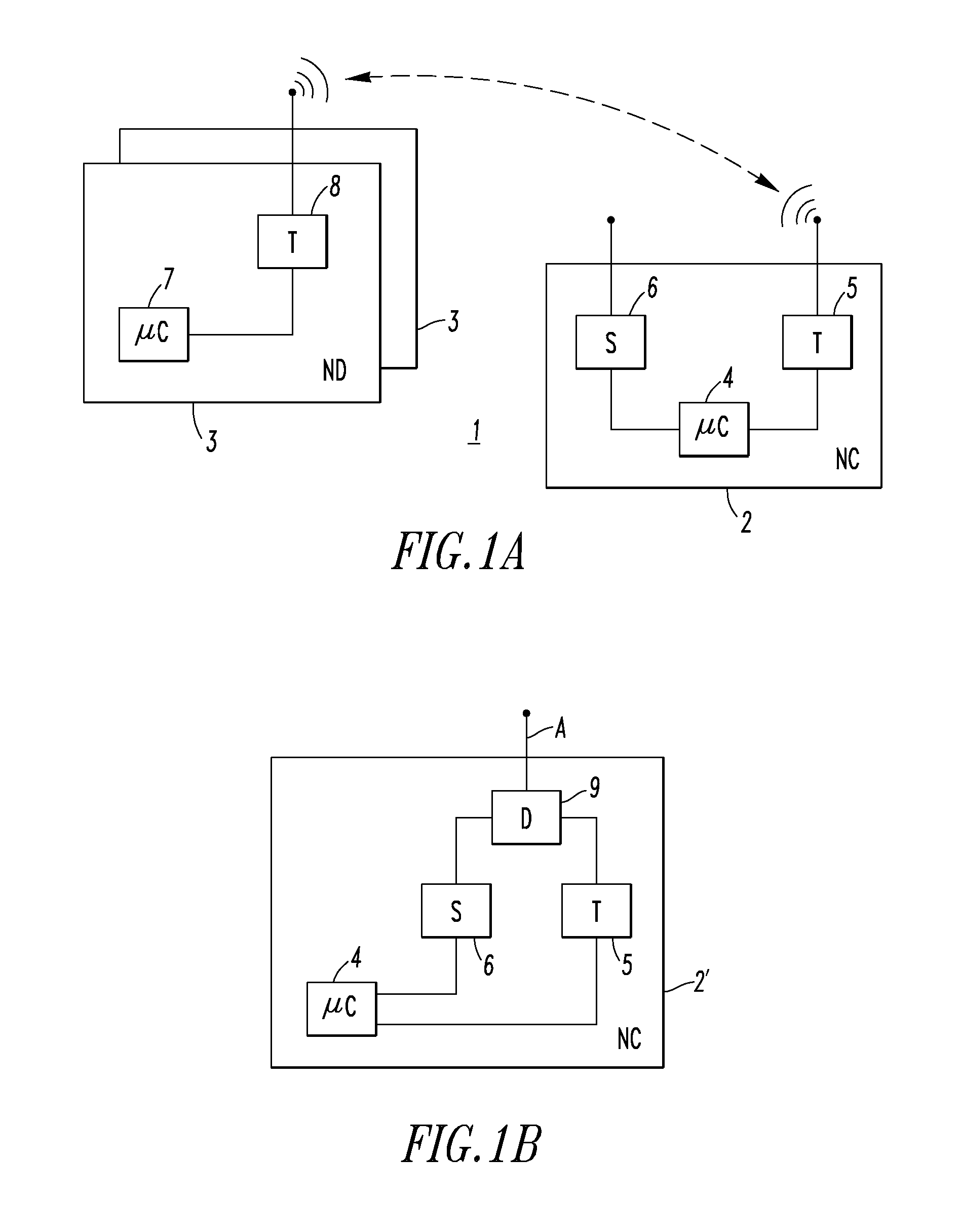
[0044]The second radio S 6 (e.g., including only a receiver) of FIG. 1A or 1B is in receive only mode, and could potentially use the same antenna A as the first radio T 5 through the use of a simple duplexer D 9 of network coordinator 2′, as shown in FIG. 1B.

Example

EXAMPLE 2

[0045]If a power amplifier (PA) (not shown) is used to transmit, then the radio receivers of the radios 5,6 must be disabled (e.g., switched out) during transmission to prevent excess power from damaging the circuitry. For example, the example radio T 5 employs a single channel for transmit and receive (half duplex); hence, “listen-while-talking” is not supported. It may also be necessary to disable the receiver of the second radio S 6 during transmit by the first radio T 5 to avoid adjacent channel desensitization (as shown in FIG. 6).

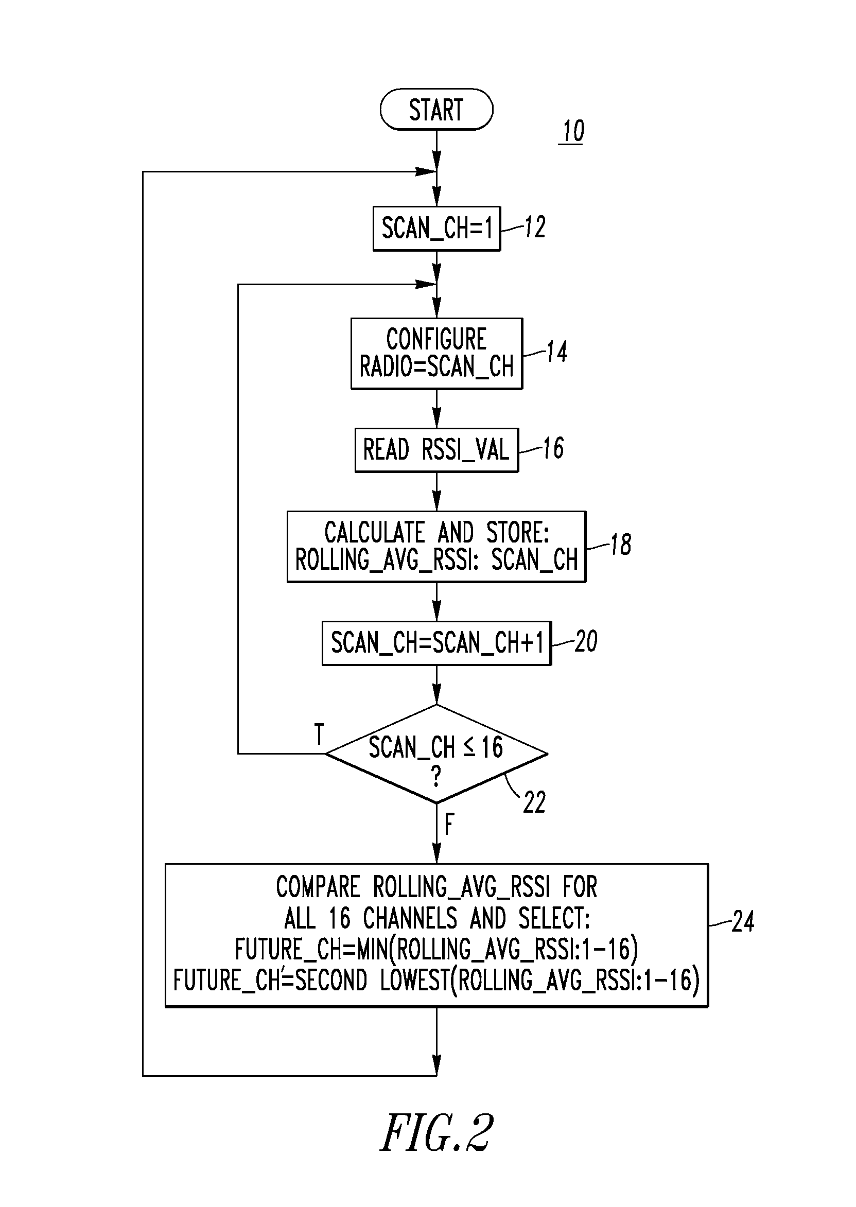
[0046]Referring to FIG. 2, a Future Channel Assessment (and Selection) Algorithm 10 is shown. Here, the second radio S 6 (e.g., receiver) of the NC 2 of FIG. 1A is employed to monitor the background noise level of each channel, and preferably maintain a log for one or both of the following parameters: (1) rolling average of RSSI (Receive Signal Strength Indicator); and (2) peak RSSI in or about, for example, the last 24 hours.

Example

EXAMPLE 3

[0047]For example, the RSSI value provides a general indication of the amount of background noise in the corresponding channel. The higher the RSSI value, the stronger the received signal. If the second radio S 6 is receiving background noise, then it is desired that the background noise be relatively low. Conversely, when a packet (message) is received, the first radio T 5 takes an RSSI reading that indicates the strength of the received signal (i.e., a higher RS SI value is better in this instance). After all channels are scanned, as shown in FIG. 2, one technique for selecting the best Future channel (FUTURE_CH) is to simply pick the channel that has the lowest rolling average RSSI (e.g., the channel that has the lowest average background noise). The channel with the second lowest rolling average RSSI (FUTURE_CH′) can also be identified.


PUM


Abstract

A method of dynamic channel selection for a wireless communication network employs a first wireless communication channel of a first wireless radio of each of a network coordinator and a number of network devices for wireless communication therebetween. A number of different second wireless communication channels are monitored with a second wireless radio of the network coordinator. One of the different second wireless communication channels is selected as a function of background noise level or message traffic. The first wireless communication channel is monitored with the first wireless radio of the network coordinator. The first wireless communication channel is determined to have unsatisfactory quality and an identification of the selected one of the different second wireless communication channels is responsively broadcast to the network devices. The selected one of the different second wireless communication channels is employed for wireless communication between the network coordinator and the network devices.

Description

BACKGROUND OF THE INVENTION[0001]1. Field of the Invention[0002]This invention relates generally to communication networks and, more particularly, to wireless communication networks employing a network coordinator, such as a base station, and network devices, such as input sensors and / or output devices. The invention also relates to methods for wireless communication in a wireless communication network and, more particularly, to methods for channel selection.[0003]2. Background Information[0004]Wireless communication networks are an emerging new technology, which allows users to access information and services electronically, regardless of their geographic position.[0005]All nodes in ad-hoc wireless communication networks are potentially mobile and can be connected dynamically in an arbitrary manner. All nodes of these networks behave as routers and take part in discovery and maintenance of routes to other nodes in the network. For example, ad-hoc wireless communication networks are...

Claims


Application Information

Patent Timeline
IPC IPC(8): H04B7/00
CPCH04W72/085H04W72/542
Inventor LUEBKE, CHARLES J.
Owner EATON CORP
Why Eureka
Try Eureka