
Cable assembly having bend performance optical fiber slack coil

Active Publication Date: 2008-05-15
CORNING OPTICAL COMM LLC
View PDF11 Cites 20 Cited by
  • Summary
  • Abstract
  • Description
  • Claims
  • Application Information

AI Technical Summary

Benefits of technology

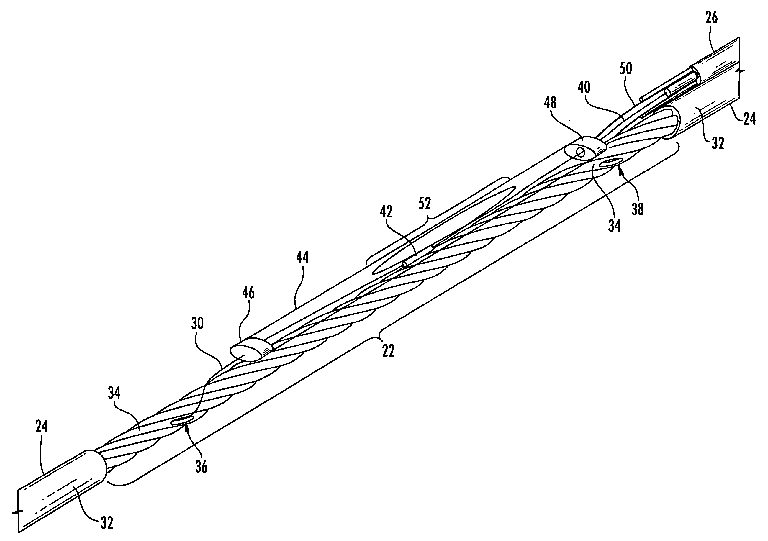
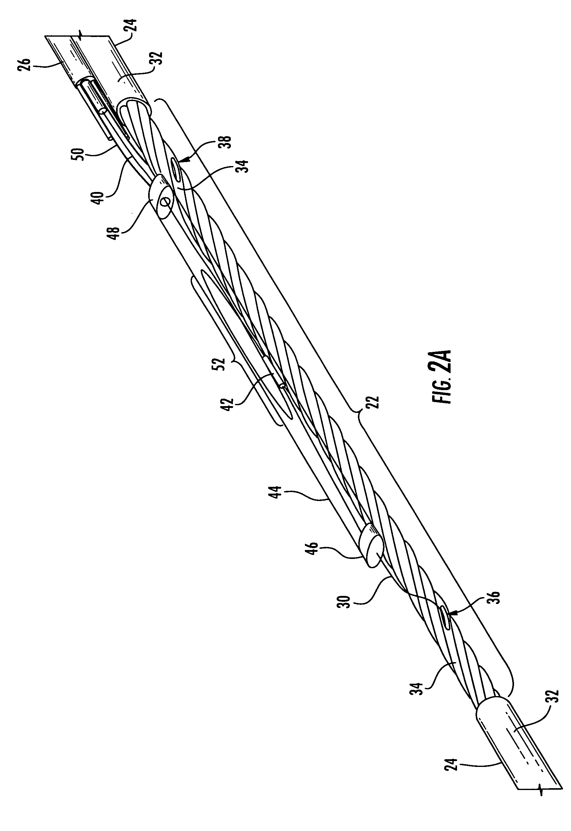
[0008]To achieve the foregoing and other objects, and in accordance with the purposes of the invention as embodied and broadly described herein, the present invention provides various embodiments of a fiber optic cable assembly including a fiber optic cable and at least one mid-span access location along the cable length for providing access to at least one preterminated optical fiber of the cable. The at least one preterminated optical fiber of the cable is routed away from the remaining uncut fibers of the cable and spliced or otherwise optically coupled to at least one other optical fiber. The at least one other optical fiber may be maintained within a tether or may be an optical fiber of a drop cable, both of which are referred to herein as a “tether.” The tether is secured about a first end to a flexible encapsulating body, referred to herein as an “overmolded body”, about the mid-span access location, and terminates at a second end at splice ready fibers, connectorized fibers, tethered assembly or the like. The overmolded body includes a slack coil or loop of optical fiber within. The largest cross-sectional diameter of the cable assembly is preferably less than about 2 inches, more preferably less than about 1.5 inches, and even more preferably less than about 1.25 inches. The slack coil may be maintained within a splice tube or within a portion of the overmolded body. The slack coil is advantageous in that it provides slack sufficient to accommodate tensile and temperature induced fiber length changes and allows the fibers to move within the tube as the cable assembly is bent. Bend performance fibers are used to reduce the diameter of the assembly while allowing for a slack coil of optical fiber.
[0010]In various embodiments, the bend performance fiber is microstructured optical fiber comprising a core region and a cladding region surrounding the core region, the cladding region comprising an annular hole-containing region comprised of non-periodically disposed holes such that the optical fiber is capable of single mode transmission at one or more wavelengths in one or more operating wavelength ranges. The core region and cladding region provide improved bend resistance, and single mode operation at wavelengths preferably greater than or equal to 1500 nm, in some embodiments also greater than 1400 nm, in other embodiments also greater than 1260 nm. The optical fiber provides a mode field at a wavelength of 1310 nm preferably greater than 8.0 microns, more preferably between 8.0 and 10.0 microns. In preferred embodiments, optical fiber disclosed herein is thus single-mode transmission optical fiber.

Problems solved by technology

Rigid closures are typically inflexible to a variety of installation environments and are typically too large to be successfully installed within small diameter conduit.
Additional strength and bending elements are undesirable in that they require an added element, potentially form a tear point and do not always prevent a mid-span access point from flipping over, especially at high tensile loads.
While the '665 closure is a straight through design for small diameter installation environments, it is a requirement that it be sized small enough so that it cannot accommodate a slack coil.
The '812 closure also does not include a slack coil, and it is further an inflexible closure, making it difficult to install through conduit or around a sheave wheel.
Further, a slack coil provided using a bend performance, bend insensitive or bend optimized fiber would allow for a slack coil without increasing the size of the package, a design not possible using conventional closures and standard single mode fiber.

Method used


Image

  • Cable assembly having bend performance optical fiber slack coil
  • Cable assembly having bend performance optical fiber slack coil
  • Cable assembly having bend performance optical fiber slack coil

Examples


Embodiment Construction

[0019]The present invention will now be described more fully hereinafter with reference to the accompanying drawings in which exemplary embodiments of the invention are shown. However, the invention may be embodied in many different forms and should not be construed as limited to the embodiments set forth herein. These exemplary embodiments are provided so that this disclosure will be both thorough and complete, and will fully convey the scope of the invention and enable one of ordinary skill in the art to make, use and practice the invention. Like reference numbers refer to like elements throughout the various drawings.

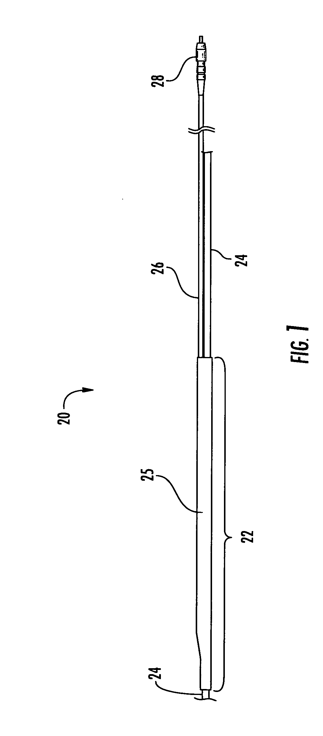
[0020]Referring to FIG. 1, a fiber optic cable assembly 20 of the present invention includes at least one mid-span access location 22 along the cable length for providing access to at least one optical fiber within the cable. In preferred embodiments, the cable assembly 20 includes a distribution cable 24 including a plurality of mid-span access locations 22 at prede...


PUM


Abstract

A fiber optic cable assembly including a mid-span access location, a cable having at least fiber therein, and a tether attached and spliced to at least one fiber of the cable. The access location and portions of the cables are substantially encapsulated within a flexible body having dimensions sufficient to accommodate a slack coil or loop of bend performance optical fiber therein. A method for making a fiber optic cable assembly including an access location, distribution cable, tether and slack coil of optical fiber maintained within a flexible overmolded body while providing an assembly having a cross-sectional diameter less than about 1.25 inches.

Description

BACKGROUND OF THE INVENTION[0001]1. Field of the Invention[0002]The present invention relates generally to a cable assembly for use in an FTTx optical network, and more specifically, to a low-profile fiber optic cable assembly including a flexible cable access location, tether and slack coil utilizing bend performance optical fiber.[0003]2. Description of the Related Art[0004]Engineered fiber optic cable assemblies are being developed to deliver services to subscribers over optical networks. These networks are commonly referred to as “FTTx” networks, wherein “FTT” stands for “Fiber-to-the” and “x” is used to generically describe a location such as a premises, home, office, desk, building, etc. An engineered cable assembly typically includes at least one mid-span access location, or tap point, at a predetermined position along the cable length at which one or more pre-selected optical fibers are preterminated and routed away from the remaining uncut optical fibers of the cable, typic...

Claims


Application Information

Patent Timeline
IPC IPC(8): G02B6/44G02B6/255
CPCG02B6/4475G02B6/4454
Inventor LEWALLEN, CHRISTOPHER PAULELKINS, ROBERT B.LUTHER, JAMES P.SARAVANOS, COSTASARAVANOS, ELLI MAKRIDES
Owner CORNING OPTICAL COMM LLC
Learn More