Method of storage of sequestered greenhouse gasses in deep underground reservoirs

a technology of sequestered greenhouse gas and deep underground reservoir, which is applied in the directions of transportation and packaging, survey, borehole/well accessories, etc., can solve the problems of difficult prediction of their specific suitability for storage at best, uneconomical transportation of ghg to the storage site, etc., and achieve the effect of allowing low viscosity diffusivity

Inactive Publication Date: 2008-05-15
TERRAWATT HLDG CORP
View PDF33 Cites 41 Cited by
  • Summary
  • Abstract
  • Description
  • Claims
  • Application Information

AI Technical Summary

Benefits of technology

[0022]One embodiment of the present invention provides a location for CO2 storage that is available in most all areas of the world in deep crystalline rock in which leak proof artificial reservoirs can be generated. Such formations are typically Precambrian rocks that are found almost everywhere around the globe, and are generally located at depths greater than sedimentary geologic strata. These deep artificial reservoirs in crystalline rock are beneficial for several reasons. First, these deep seated crystalline rock formations are relatively p

Problems solved by technology

The most likely suitable subsurface formations, sedimentary formations, will have regional characteristics that make predicting their specific suitability for storage very difficult at best.
The results of storing GHG in these formations may not be known for years after the expense to inject the GHG, and this poses significant risks not only from reservoir seal leaks, but also from the fact that even once a suitabl

Method used


Image

  • Method of storage of sequestered greenhouse gasses in deep underground reservoirs
  • Method of storage of sequestered greenhouse gasses in deep underground reservoirs
  • Method of storage of sequestered greenhouse gasses in deep underground reservoirs

Examples


cased well

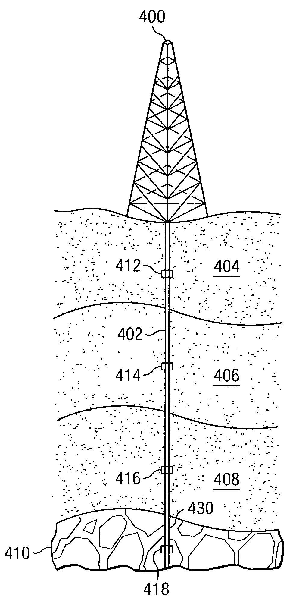
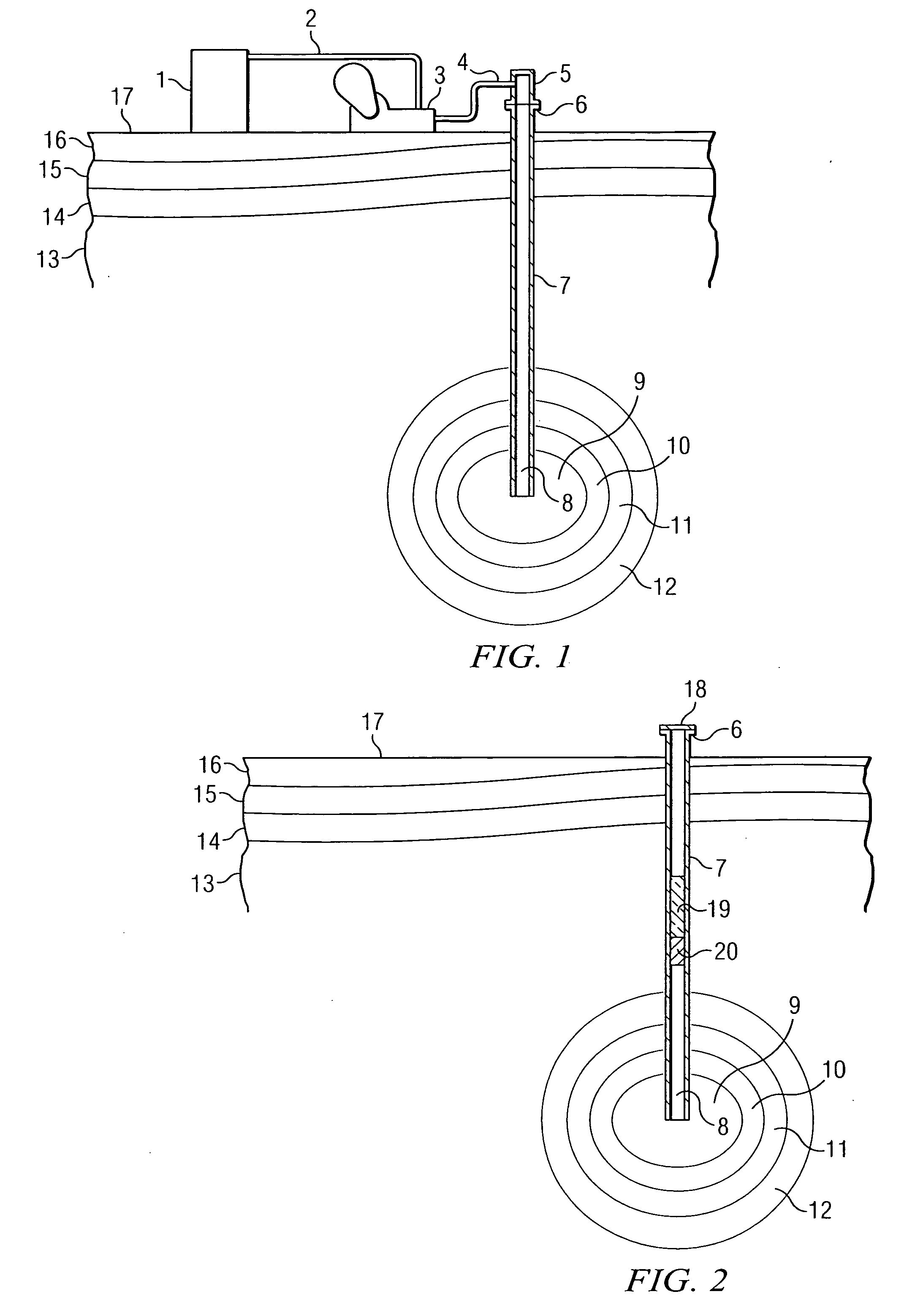
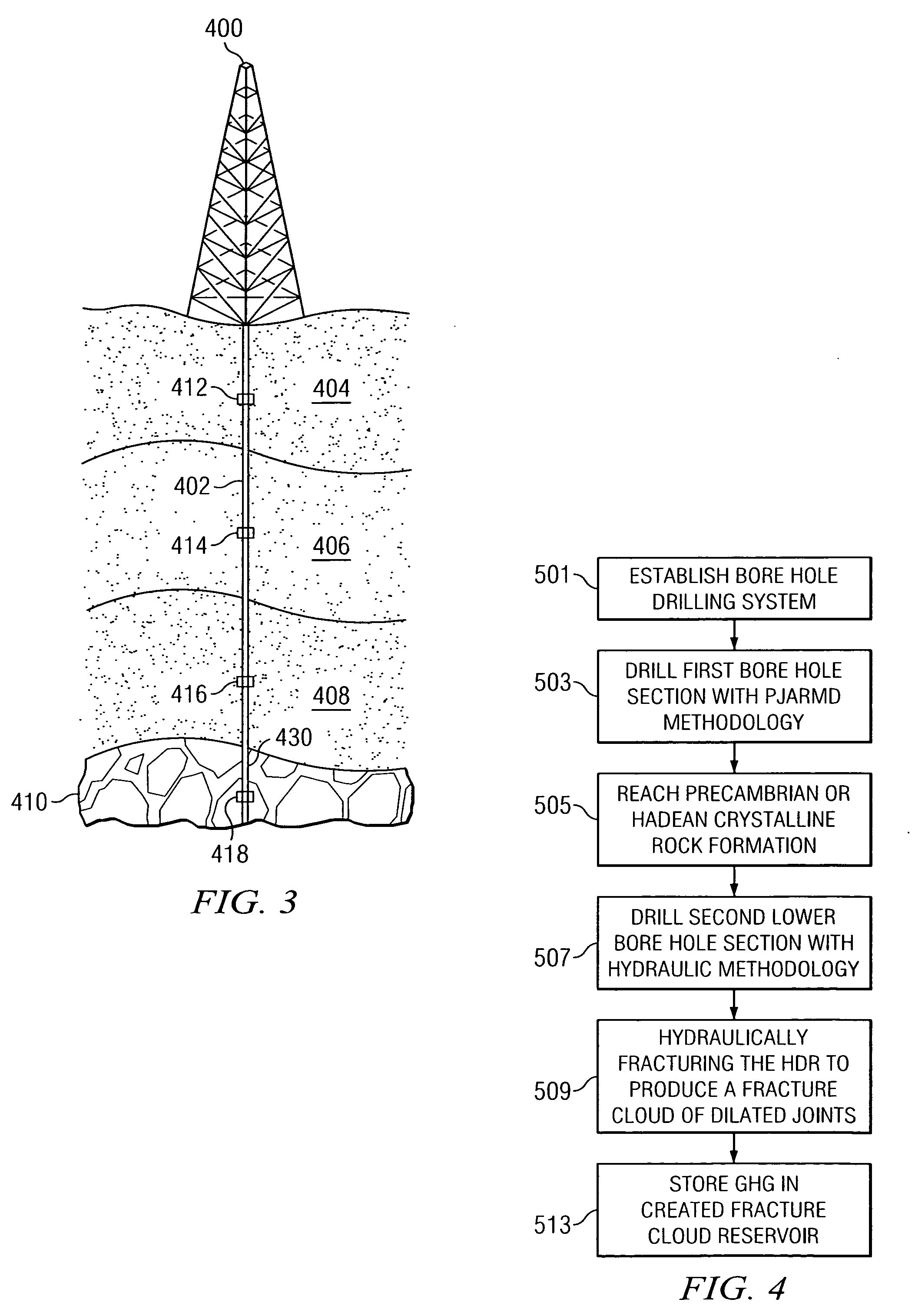
[0045 bore 7 is located in close proximity to GHG capture means 1. Cased well bore 7 is drilled from the surface 17 utilizing Particle Jet Drilling means through sedimentary formations 16, 15 and 14 into Precambrian crystalline formation 13 to the shallowest depth necessary to achieve a combination of temperature and pressure sufficient to provide a transition from an unacceptable level of a brittle failure mode to an acceptable plastic failure mode generally believed to be a temperature of at least of 250° C. The well bore 7 is cased and a reservoir 9 formed through any means that would provide the porosity and permeability necessary for GHG storage. Such means to generate the artificial reservoir 9 could encompass but not be limited to the injection of a fluid to hydraulically dilate the existing joints within the formation such as is used in Hot Dry Rock reservoir generation methods to a high energy pulse stress fracturing forces generated from underground conventional or thermo-...


PUM


Abstract

A system and method for storage of Greenhouse Gasses, in particular CO2 gasses, in an underground reservoir of rock at the shallowest depth necessary to achieve a combination of temperature and pressure sufficient to ensure that the reservoir is hydraulically sealed and isolated. Particle Jet Drilling is utilized to afford an economical process of drilling the necessary deep well bores to reach the deep rock formations. The underground reservoirs are formed through hydraulic dilation of existing joints in the rock formations.

Description

CROSS-REFERENCE TO RELATED APPLICATIONS[0001]This patent application claims priority from and incorporates by reference the entire disclosure of U.S. Provisional Patent Application No. 60 / 841,875, filed on Sep. 1, 2006. This patent application incorporates by reference the entire disclosures of U.S. Provisional Patent Application No. 60 / 582,626, filed on Jun. 23, 2004, U.S. Provisional Patent Application No. 60 / 650,667, filed on Feb. 7, 2005, and U.S. patent application Ser. No. 10 / 581,648, filed on Jun. 1, 2006. This patent application claims priority from and incorporates by reference the entire disclosure of U.S. Provisional Patent Application 60 / 930,403, filed on May 16, 2007.BACKGROUND OF THE INVENTION[0002]1. Field of the Invention[0003]The present invention relates to the storage of sequestered Greenhouse Gas (“GHG”) and, more particularly, but not by way of limitation, to the development of Deep Underground Reservoirs in crystalline rock utilizing bore hole generation (drill...

Claims


Application Information

Patent Timeline
IPC IPC(8): B65G5/00
CPCB65G5/00E21B7/18Y02C10/14E21B43/164E21B41/0064Y02P90/70Y02C20/40
Inventor CURLETT, HARRY B.
Owner TERRAWATT HLDG CORP
Why Eureka
Try Eureka