Light coupling structure on light guide plate in a backlight module

a backlight module and light coupling technology, applied in the field of backlight modules, can solve problems such as reducing illumination, and achieve the effects of reducing the thickness of the entire backlight module, increasing brightness uniformity, and eliminating distan

Inactive Publication Date: 2008-12-09
INNOLUX CORP
View PDF29 Cites 13 Cited by
  • Summary
  • Abstract
  • Description
  • Claims
  • Application Information

AI Technical Summary

Benefits of technology

[0008]The light guide plate with convex structures using LEDs as a light source, of the present invention eliminates the distance between the LEDs and the light guide plate, thus reducing the thickness of the entire backlight module. Additionally, brightness uniformity increases, and a diffusion sheet with lower diffusivity can be used, thus increasing illumination intensity over the entire diffusion sheet.

Problems solved by technology

Recently, liquid crystal displays (LCD) have replaced cathode ray tube (CRT) displays in the mainstream market, due to lower output radiation and thin profile.
To prevent this problem, a diffusion sheet with high brume must be employed, this, however, results in reduced illumination.

Method used


Image

  • Light coupling structure on light guide plate in a backlight module
  • Light coupling structure on light guide plate in a backlight module
  • Light coupling structure on light guide plate in a backlight module

Examples


Embodiment Construction

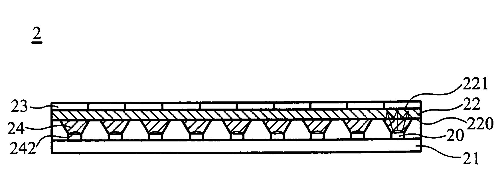
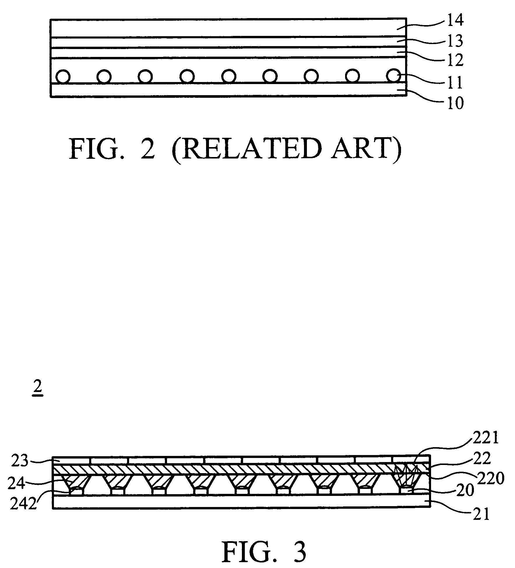
[0018]FIG. 3 is a cross-section of the present invention. In the present invention, the backlight module includes plurality of LEDs 20 and a light guide plate 22.

[0019]The LEDs 20 serve as point light sources and are arrayed on a base plate 21. The light guide plate 22 is made of polymethylmethacrylate (PMMA) or polycarbonate (PC) and has a first surface 220 and a second surface 221 parallel to the first surface 220. Wherein the first surface 220 has a plurality of convex structures 24 corresponding to the LEDs 20, as shown in Fig 4, the convex structure 24 is formed in a flat frustum shape or truncated cone shape, and the convex structure 24 has a proximal end portion 240 and a distal end portion 241, wherein the cross section area of the proximal end portion 240 is larger than the cross section area of the distal end portion 241. Furthermore, there is a dome-shaped recess 242 formed at the distal end portion 241 of the convex structure 24, to increase light diffusion uniformity. T...


PUM

PropertyMeasurementUnit
two dimensionalaaaaaaaaaa
frustum shapeaaaaaaaaaa
shapeaaaaaaaaaa

Abstract

An apparatus of a backlight module and a liquid crystal display. The apparatus includes a plurality of point light sources and a light guide plate. The plurality of point light sources is positioned on a base plate. The light guide plate has a first surface and a second surface parallel to the first surface. The first surface of the light guide plate has a plurality of convex structures corresponding to the point light sources, every convex structure has a distal end portion, and an arc-shaped recess formed therein.

Description

BACKGROUND OF THE INVENTION[0001]1. Field of the Invention[0002]The present invention relates to a backlight module and especially a backlight module for use in a liquid crystal display (LCD) device.[0003]2. Description of the Related Art[0004]Recently, liquid crystal displays (LCD) have replaced cathode ray tube (CRT) displays in the mainstream market, due to lower output radiation and thin profile. Generally speaking, cold cathode fluorescent lamps (CCFLs) are used as light sources in traditional LCD backlight modules.[0005]FIG. 1 shows an exploded view of the traditional backlight module. The backlight module is disposed below an LCD panel 14. The traditional backlight module includes a reflector 10, a plurality of CCFLs 11, a light guide plate 12, and a diffusion sheet 13. FIG. 2 is a combined view. Light emitted by the CCFL is bounces off the reflector 10 and exits the backlight module through the diffusion sheet 13 providing light to the LCD panel 14.[0006]In conventional back...

Claims


Application Information

Patent Timeline
Patent Type & Authority Patents(United States)
IPC IPC(8): G02F1/1335G09G3/36
CPCG02B6/0021G02F1/133603
Inventor CHANG, YI-HUI
Owner INNOLUX CORP
Why Eureka
Try Eureka