
Shift Control Method For An Automatic Gearbox

a technology of automatic transmission and control method, which is applied in the direction of gearing control, gearing element, belt/chain/gearing, etc., can solve the problems of affecting the synchronization of downstream range groups, affecting the speed of the transmission, and affecting the synchronization of the downstream range groups, so as to reduce the effect of reducing the size of the shifting clutch

Active Publication Date: 2008-05-15
ZF FRIEDRICHSHAFEN AG
View PDF8 Cites 12 Cited by
  • Summary
  • Abstract
  • Description
  • Claims
  • Application Information

AI Technical Summary

Benefits of technology

[0022]In this way, it is advantageously guaranteed that without any additional component, the range group is automatically synchronized or the synchronization of the range group is supported and consequently accelerated, due to which the entire shifting sequence is quickened. The method of the invention can moreover be used, when a synchronized shifting clutch is used in the range group, to reduce the size of the shifting clutch to a smaller gauge and therewith to configure it more compactly and more cheaply. As an alternative to this, the method of the invention also enables the use of an unsynchronized shifting clutch in the range group.

Problems solved by technology

Since almost simultaneous shifting of the main transmission and the range group is difficult to bring about manually, the range groups of known range group transmissions are usually shifted automatically using synchronized shifting clutches.
But the disadvantage is that acceleration of the shifting sequence, especially within a range group, is possible only with a considerable expenditure in equipment.
Thus a synchronizing apparatus must be provided for accelerating the shifting process in the range group, such as a transmission brake, to retard and an auxiliary drive to accelerate the input shaft of the range group which, however, only comes into question for special motor vehicles due to space and cost reasons.
The synchronization of the downstream range group is, nonetheless in this way, disadvantageously made difficult and delayed due to the great rotational speed difference and the higher moments of inertia associated with the input shaft of the range group.

Method used


Image

  • Shift Control Method For An Automatic Gearbox
  • Shift Control Method For An Automatic Gearbox
  • Shift Control Method For An Automatic Gearbox

Examples


Embodiment Construction

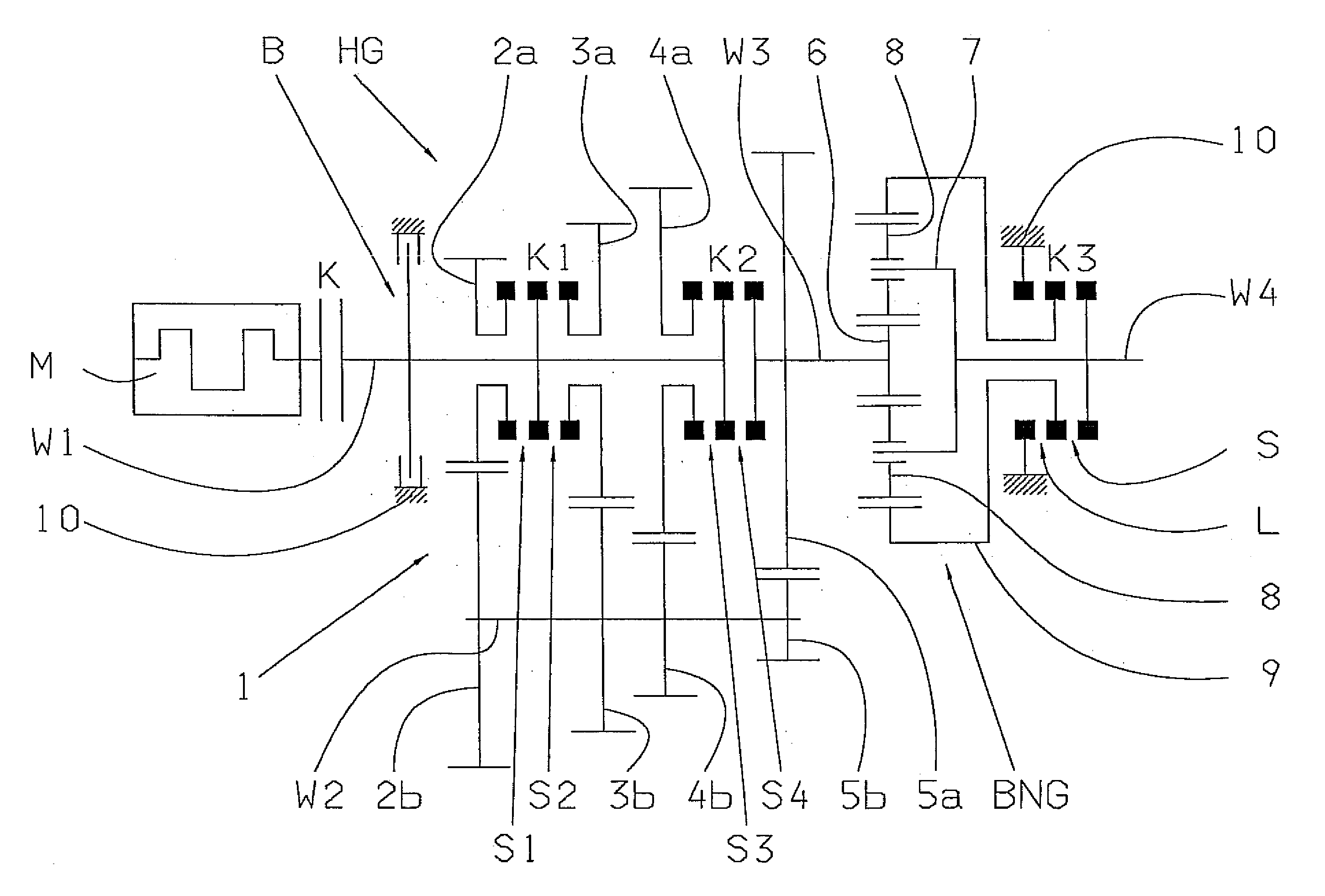
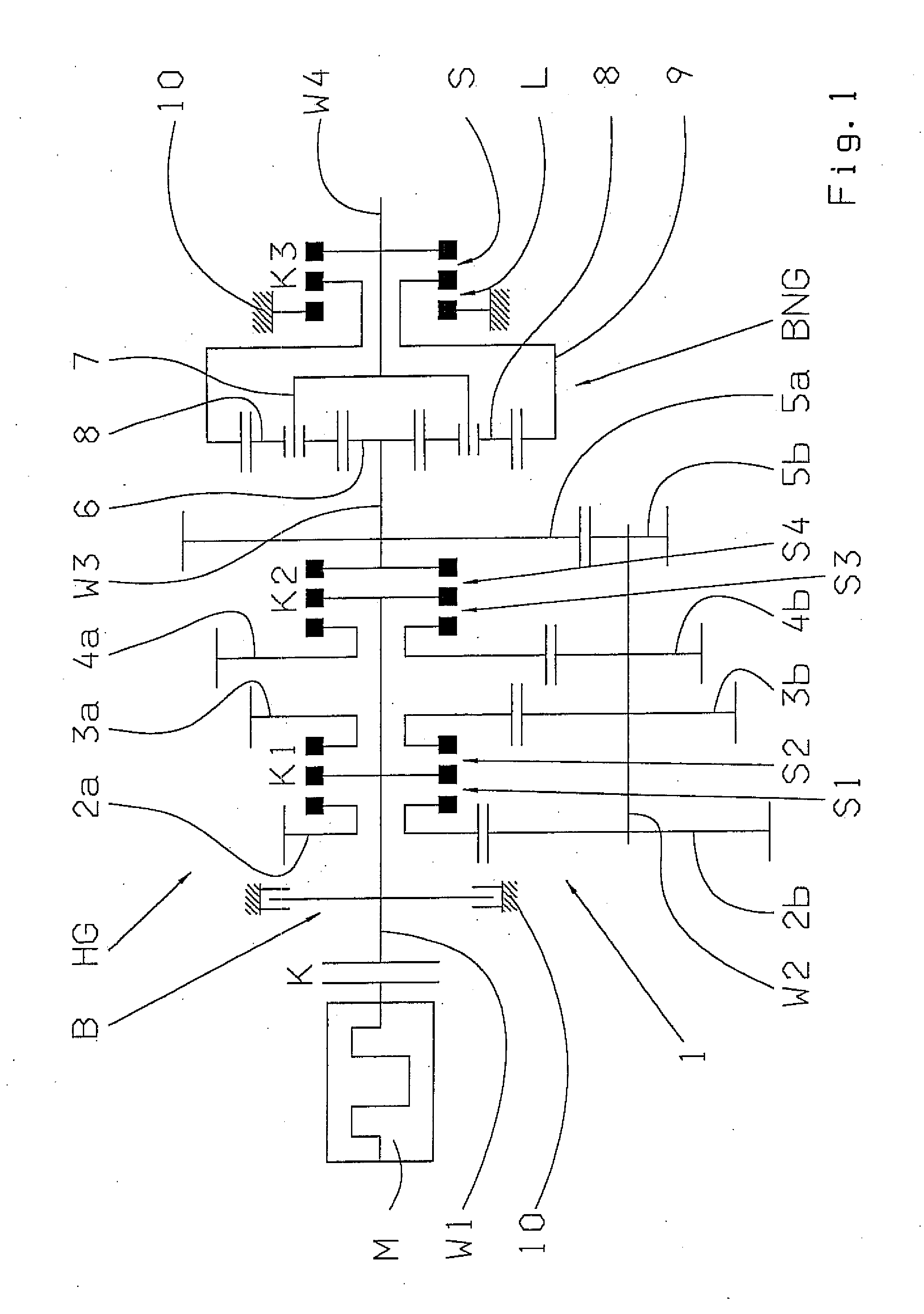
[0037]An automatic transmission in accordance with FIG. 1 is constructed as a range group transmission 1 with a main transmission HG and a range group BNG downstream from this. The main transmission HG is in connected with its input shaft W1, via a controllable startup and shifting clutch K, to a drive motor M, constructed as an internal combustion motor. Furthermore, the main transmission HG has a transmission brake B on the input shaft W1.

[0038]The main transmission HG is presently constructed as a four-stage spur gear transmission in gearbox design and has, beside the input shaft W1, a countershaft W2, an output shaft W3 and two shifting clutches K1, K2 arranged on the input shaft. Three pairs of gears 2a, 2b; 3a, 3b; 4a, 4b are respectively arranged with a loose gear 2a, 3a, 4a on the input shaft W1 and, in each case, with a fixed gear 2b, 3b, 4b on the countershaft W2. Of these the first gear pair 2a, 2b has a large gear ratio >1; the second gear pair 3a, 3b has a medium gear r...


PUM


Abstract

A shift control method of a range group transmission with a multi-speed main transmission, which connects with a drive motor, via a clutch (K) and an input shaft. A transmission brake optionally engages the input shaft. At least a two range group is located downstream of the main transmission. A range change shift is accomplished by changing a gear of the main transmission and the range group. The shifting sequence is accelerated by: reducing motor torque and disengaging the clutch (K); disengaging a previous range group gear; synchronizing a new range group gear; disengaging a previous main transmission gear; engaging the new range group gear; synchronizing a new main transmission gear; engaging the new main transmission gear; and engaging the clutch (K) and increasing the motor torque, such that synchronization of the new gear occurs by influencing the input shaft of the main transmission.

Description

[0001]This application is a national stage completion of PCT / EP2005 / 012874 filed Dec. 2, 2005, which claims priority from German Application Serial No. 10 2005 002 496.3 filed Jan. 19, 2005.FIELD OF THE INVENTION[0002]The invention concerns a shift control method for an automatic transmission constructed as a range group transmission, with a multi-speed main transmission which, on the input side, can be connected, via a controllable startup and shifting clutch with a drive motor, and has a transmission brake in connection with its input shaft, as well as with an at least two stage range group arranged downstream from the main transmission in terms of drive engineering, whereby a range change shift is conducted with a change of the gear ratio in the main transmission, as well as in the range group.BACKGROUND OF THE INVENTION[0003]Transmissions with a large range of narrow gear ratios are necessary, especially for use in commercial vehicles such as trucks or busses. In order to achiev...

Claims


Application Information

Patent Timeline
IPC IPC(8): B60W10/04B60W10/10B60W30/18
CPCB60W10/02B60W10/06B60W10/111B60W30/19F16H61/0403F16H61/08Y10T477/74F16H2061/0411F16H2306/48F16H2306/54Y10T477/688Y10T477/60Y10T477/6388F16H61/702
Inventor GRONER, WOLFGANGVESENJAK, ANDELKOHAFEN, THOMAS
Owner ZF FRIEDRICHSHAFEN AG
Learn More