

Thin client intelligent transportation system and method for use therein
- Summary
- Abstract
- Description
- Claims
- Application Information
AI Technical Summary
Benefits of technology
Problems solved by technology
Method used
Image

Examples
Embodiment Construction
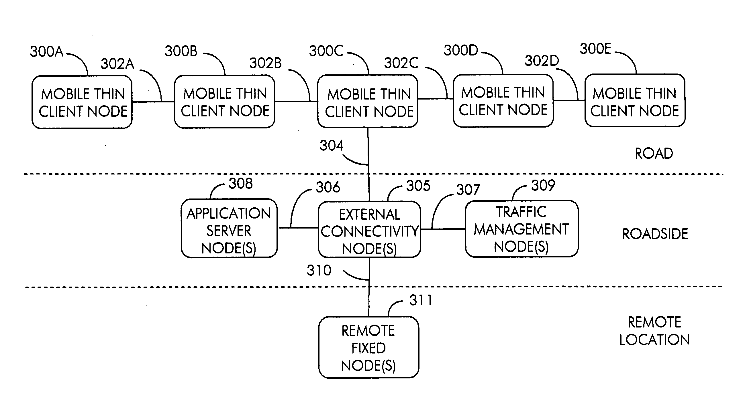
[0042]FIG. 3 shows a thin client intelligent transportation system (ITS) in which geoposition-to-road position resolution is provided by roadside nodes to improve overall system performance. In the illustrated system, mobile thin client nodes 300, such as cars, trucks, buses, motorcycles, bicycles or other vehicles that utilize roads, include on-vehicle wireless communications capability, on-vehicle geopositioning capability and on-vehicle driver notification capability. Mobile thin client nodes 300 determine their geoposition, including latitude, longitude and elevation, and transmit it to other mobile thin client nodes 300 on the road through a wireless communication link 302. Mobile thin client nodes 300 also transmit their geoposition to one or more external connectivity nodes 305 at roadside through a wireless communication link 304.
[0043] It will be appreciated that the present ITS may also include one or more mobile thick client nodes, which may be cars, trucks, buses, motor...
PUM
 Abstract
Description
Claims
Application Information