Gardening shears

a shear and garden technology, applied in the field of garden shears, can solve the problems of difficulty in stably drilling the handles of users, roughness or even tears at the cut of the objective branch, and the defects of the foresaid conventional gardening shear, so as to reduce the shearing resistance, facilitate saving operation effort, and maintain proper shearing efficiency

Inactive Publication Date: 2008-05-22
NATURA INNOVATION LTD
View PDF10 Cites 5 Cited by
  • Summary
  • Abstract
  • Description
  • Claims
  • Application Information

AI Technical Summary

Benefits of technology

[0019]First, the disclosed gardening shears have three fulcrums wherein the first one is composed of the non-circular pivot hole of the first shear element and a combining portion of the pivot member that are mated mutually; the second one is the shear element pivot shaft connecting the second shear element and the handle shaft; and the third one is the shear element combining pin connecting the first shear element and second shear element. The present invention implements three fulcrums that share the force and counterforce generated during cutting a stem to protect the fulcrums from being damaged by undergoing excessive force. Thereby, the disclosed shears can keep proper shearing efficiency.
[0020]Second, according to the present invention, the opening angle of the shear elements is restricted by means of the combination of the pivot hole of the second shear element as well as the pivot member and the handles opened at the largest angle can still be easily held by a normal adult hand so that the squeezing force to avoid foresaid excessive opening of the shears can be saved. Also, as the opening angle of the shear elements is restricted, the unfavorable influence on the pivot member, shear element combining pin, and shear element pivot shaft caused by immoderate opening of the shear elements can be eliminated.
[0021]Third, when the disclosed gardening shears are implemented to cut a stem, the first handle is pulled toward the second handle to make the first shear element cut into the stem of the plant by a clockwise revolving movement that in turn affects the second shear element to swing with a predetermined angle around the stem to be cut. Thus, no squeezing force generated between the cutting blade portion of the first shear element and the anvil blade portion of the second shear element, so that a slip of the stem during cutting can be avoided. Consequently, the user doesn't have to expend a large squeezing force to make the two shear members snap at the stem securely so that the disclosed gardening shears facilitate saving operational effort.
[0022]Besides, by the swinging movement of the second shear member, the cutting blade portion of the first shear can keep cutting in a swinging way along a curve route through entire cutting operation so that the shearing resistance can be reduced and the user is permitted to cut off a stem or branch of a plant easily with economized effort.
[0023]At last, the disclosed gardening shears allow a user to cut off a stem or branch of a plant with proper strength so that the cutting operation can remain steady. As the shearing force keeps perpendicular to the stem to be cut, smooth cutting operation and neat cuts can be therefore ensured.

Problems solved by technology

However, foresaid conventional gardening shears may have defects as described below.
Thus, when the shears encounter thick or tough branches or stems of plants, the user may have to implement his extreme strength to operate the shears, and it can be difficult for the user to hole the handles stably while exerting such excessive squeezing force.
Thus, such difficult operation may in turn render undesirable sway, shakiness or deviation of the shears during shearing and as a result, roughness or even tears may occur at the cut of the objective branch.
Further, when the excessive shearing force is imposed on the branches or stems under said excessive squeezing force, an excessive counterforce may be correspondingly incurred from the sheared branch to damage the single pivot member and detrimental clearance between the shear elements may successively arise to weaken the shearing force of the shears.
Eventually, the shears can undesirably become unusable soon.
At this time, the distance of the two dispersed handles may be too large for an adult user to hold with his single hand.
Thus, the user may have to always impose a squeezing force on the handles through his operating the shears to avoid foresaid excessive opening of the shears and this consequently renders effort wasting.
This is also a problem about effort wasting.

Method used


Image

  • Gardening shears
  • Gardening shears
  • Gardening shears

Examples


Embodiment Construction

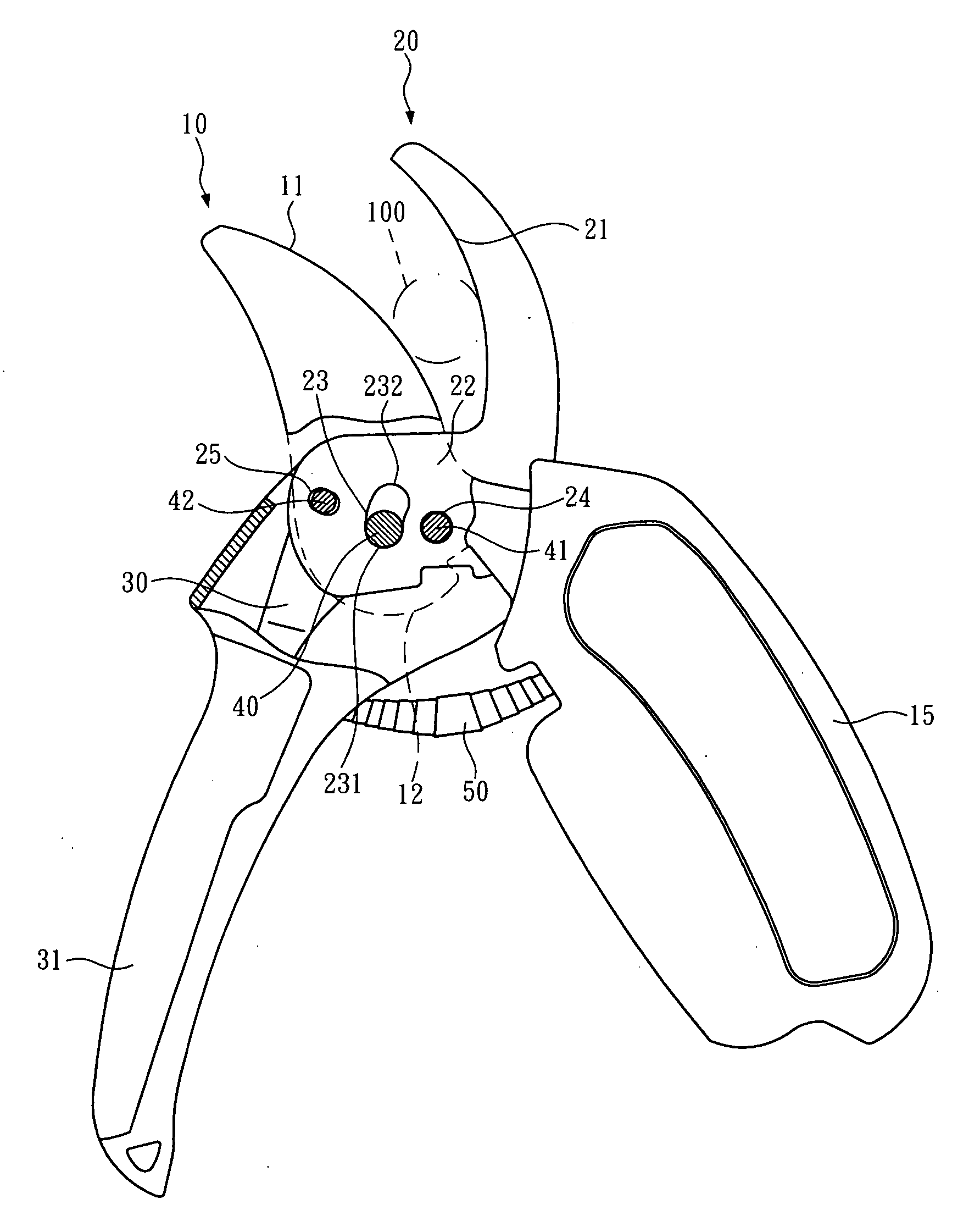
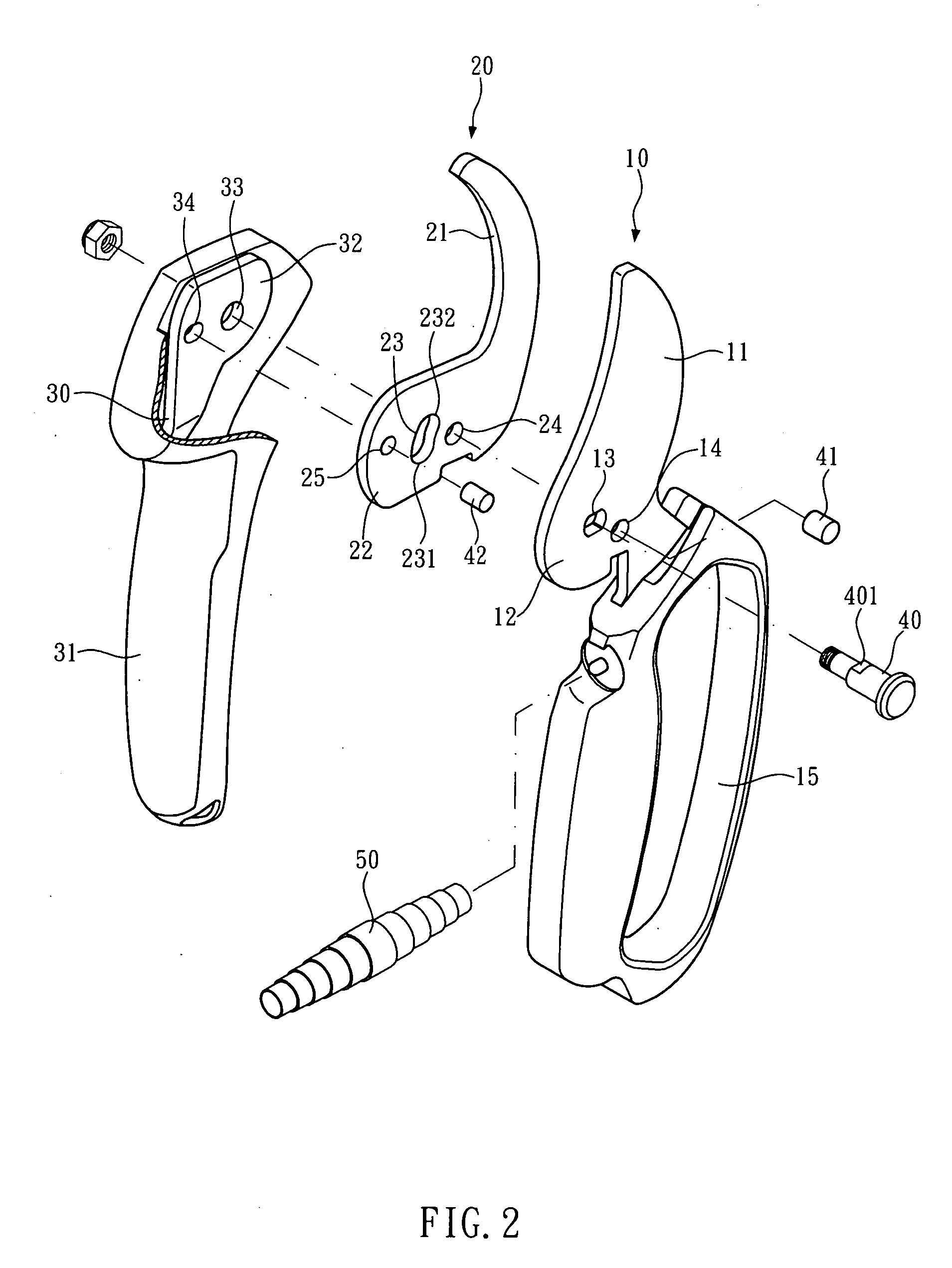
[0032]As shown in FIGS. 2 and 3, an embodiment of the disclosed effort-saving shears primarily comprises:

[0033]a first shear element 10 having a cutting blade portion 11 at one end, a combining portion 12 at the opposite end comprising a pivot hole 13 and a shear element combining hole 14, and a first handle 15 further attached to the first shear element 10;

[0034]a second shear element 20 having an anvil blade portion 21 at one end, and a combining portion 22 at the opposite end comprising a pivot hole 23 and a shear element combining hole 24 as well as a handle shaft combining hole 25 positioned respectively at the two sides of the pivot hole; wherein the pivot hole 23 is in an elliptic shape and has a first end 231 and a second end 232 at the two curve edges respectively;

[0035]a handle shaft 30 axially positioned within a second handle 31 and having a combining portion 32 at one end which comprises a pivot hole 33 and a shear element combining hole 34 wherein the combining portion...


PUM


Abstract

A pair of gardening shears comprises: a first shear element having a cutting blade portion at one end, a combining portion at the opposite end comprising a pivot hole and a shear element combining hole, and a first handle further attached to the first shear element; a second shear element having an anvil blade portion at one end, and a combining portion at the opposite end comprising a pivot hole and a shear element combining hole as well as a handle shaft combining hole a handle shaft axially positioned within a second handle; a pivot member, a shear element combining pin; and a shear element pivot shaft.

Description

BACKGROUND OF THE INVENTION[0001]1. Technical Field[0002]The present invention relates to gardening shears and, more particularly, to a pair of gardening shears for single hand holding and operating.[0003]2. Description of Related Art[0004]A pair of conventional gardening shears for single hand operating, as shown in FIG. 1, typically comprises two shear elements that are crosswise combined by a pivot member. Further, one handle may be attached to each shear element at the end beyond said pivot member. When operating such conventional gardening shears, a user squeezes both handles with single hand to drive the shear elements to approach each other and a shearing force can therefore be generated for pruning or cutting branches or stems of plants.[0005]However, foresaid conventional gardening shears may have defects as described below.[0006]Since such a pair of conventional shears has only one pivot member to function as a fulcrum, the shearing force of the shears is utterly derived f...

Claims


Application Information

Patent Timeline
Patent Type & Authority Applications(United States)
IPC IPC(8): B26B13/00
CPCA01G3/02
Inventor SHAN, SU-HUA
Owner NATURA INNOVATION LTD
Why Eureka
Try Eureka