X-y axis dual-mass tuning fork gyroscope with vertically integrated electronics and wafer-scale hermetic packaging

a technology of x-y axis and tuning forks, applied in the field of can solve the problems of inability to drive two masses with equal and opposite velocities, disadvantages, and inability to fully realize the common mode rejection of two mass in-plane angular velocity sensors, so as to improve common mode rejection, improve measurement accuracy, and reduce cost

Active Publication Date: 2008-05-22
INVENSENSE
View PDF36 Cites 61 Cited by
  • Summary
  • Abstract
  • Description
  • Claims
  • Application Information

AI Technical Summary

Benefits of technology

[0012] Accordingly, it is an object of the invention to provide an in-plane angular velocity sensor having improved measurement accuracy due to mechanically constraining the two masses to move in opposite directions, thereby improving common mode rejection.
[0013] Another object of the invention is to provide an angular velocity sensor having reduced cost due to vertical integration of sense and drive electronics.
[0014] A further object of the invention is to provide an angular velocity sensor having low cost hermetic packaging.
[0015] Yet another object of the invention is to provide an angular velocity sensor having improved performance due to the use of bulk MEMS technology providing larger proof masses having increased travel distance.
[0016] Another object of the invention is to provide an angular velocity sensor having improved performance and reduced cost by use of torsionally mounted and electrostatically driven plates having lever arms attached to the masses, to increase mass travel distance.
[0017] A further object of the invention is to provide a low cost dual axis in-plane gyroscope module having an X axis angular velocity sensor and a Y axis angular velocity sensor integrated onto the same device die.

Problems solved by technology

Any deviation from a condition of equal and opposite velocities is disadvantageous, since such deviation reduces the desired response to the Coriolis forces, and increases the undesired response to linear acceleration.
However, in practice it is not straightforward to drive two masses with equal and opposite velocities.
As a result, known two mass in-plane angular velocity sensors have not fully realized the common mode rejection promised by two mass configurations.

Method used


Image

  • X-y axis dual-mass tuning fork gyroscope with vertically integrated electronics and wafer-scale hermetic packaging
  • X-y axis dual-mass tuning fork gyroscope with vertically integrated electronics and wafer-scale hermetic packaging
  • X-y axis dual-mass tuning fork gyroscope with vertically integrated electronics and wafer-scale hermetic packaging

Examples


first embodiment

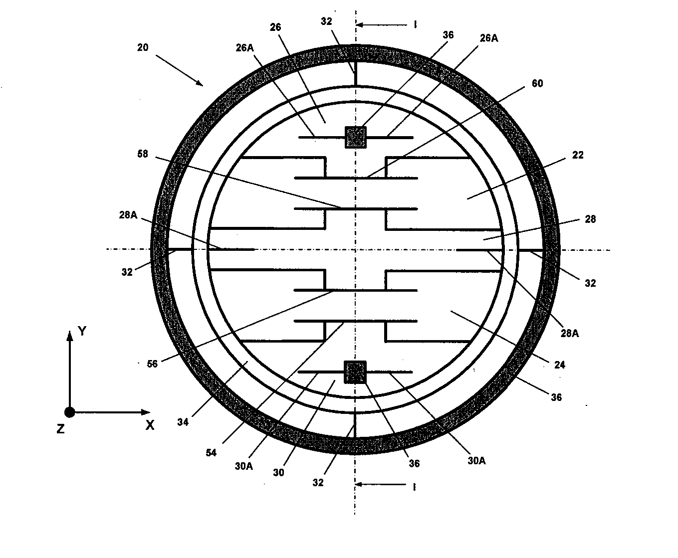
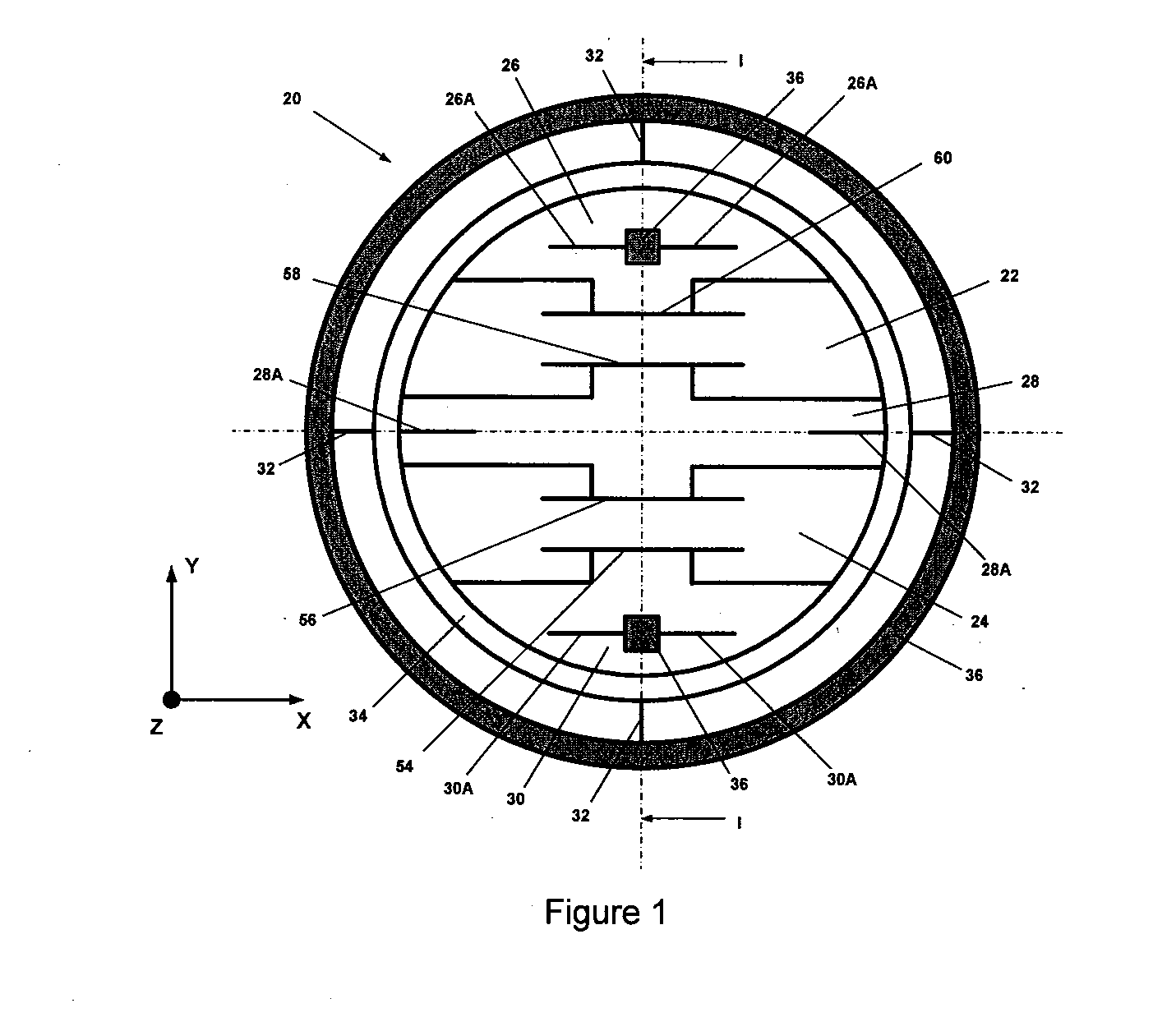
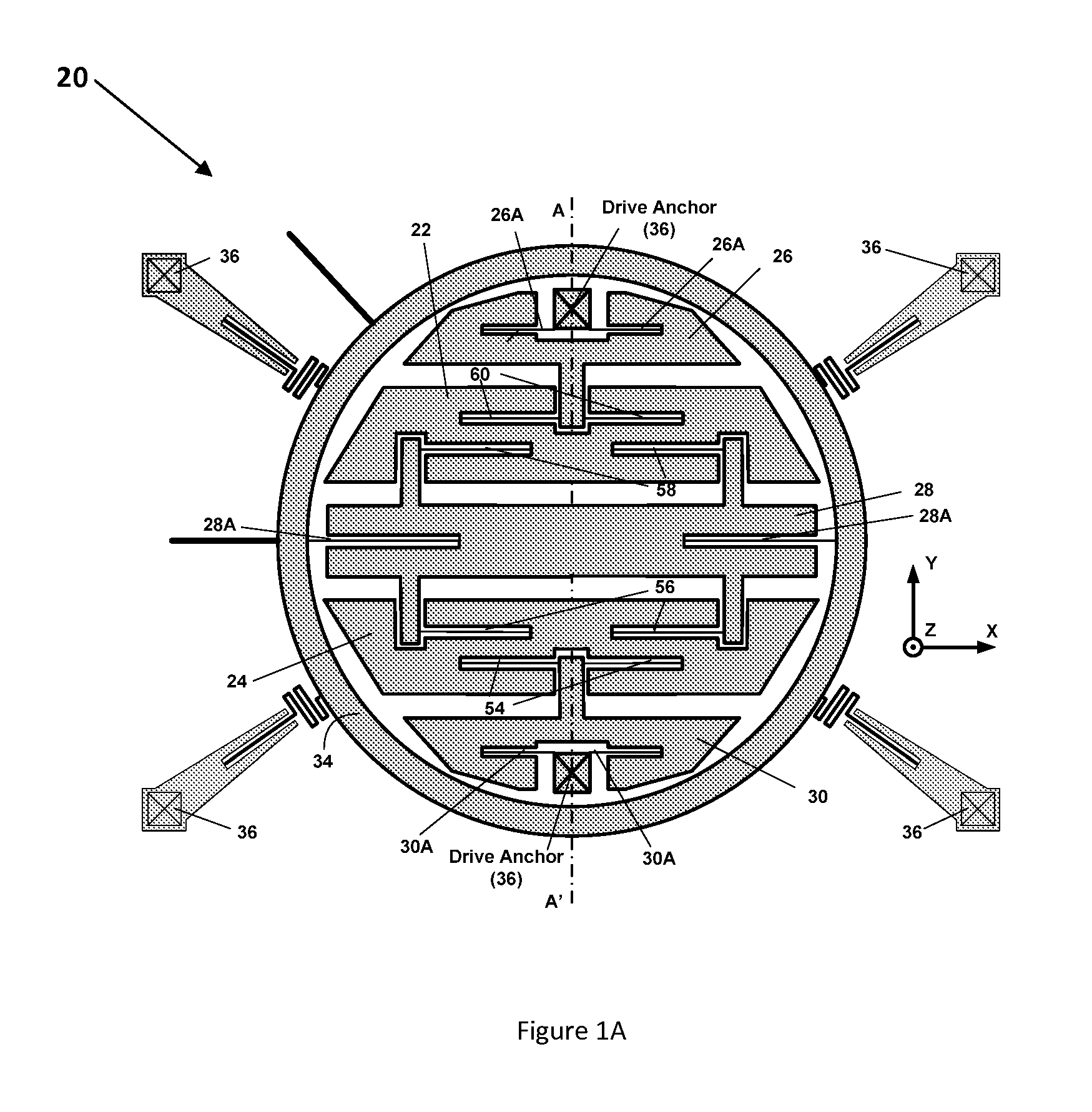
[0041]FIG. 1A is a mechanical configuration of the gyroscope wafer 20 of FIG. 1.

second embodiment

[0042]FIG. 1B is a mechanical configuration of a gyroscope wafer 20. In this embodiment flexures 54 and 55, and flexures 58 and 60 are flipped over from that of FIG. 1A thereby increasing the effective distance of the proof masses 22 and 24 from the center of the plate 28 therefore providing more sensitivity.

[0043]FIG. 1C is a third embodiment of a mechanical configuration of a gyroscope wafer 20. In this wafer 20, the frame 34 is suspended to the base 36 through four points 65a-65d, and edge plates 26 and 30 suspended to the base 36 through two the drive anchor portions. Accordingly, in the third embodiment, the number of drive anchor points to the base is reduced to two. This reduces the amount the package effects to the sensor parameters.

[0044] Two exemplary electrode configurations suitable for sensing and / or driving relative angular motion of frame 34 with respect to base 36 are schematically illustrated on FIG. 5 as 38A, 38B, and 38C and 40A, 40B, and 40C. These, or similar, ...


PUM


Abstract

An angular velocity sensor has two masses which are laterally disposed in an X-Y plane and indirectly connected to a frame. The two masses are linked together by a linkage such that they necessarily move in opposite directions along Z. Angular velocity of the sensor about the Y axis can be sensed by driving the two masses into Z-directed antiphase oscillation and measuring the angular oscillation amplitude thereby imparted to the frame. In a preferred embodiment, the angular velocity sensor is fabricated from a bulk MEMS gyroscope wafer, a cap wafer and a reference wafer. In a further preferred embodiment, this assembly of wafers provides a hermetic barrier between the masses and an ambient environment.

Description

CROSS-REFERENCE TO RELATED APPLICATIONS [0001] Under 35 U.S.C. §120, this application is a Continuation in Part of U.S. patent application Ser. No. 11 / 283,083, filed Nov. 18, 2005. This application is also related to U.S. patent application Ser. No. 10 / 690,224 filed Oct. 20, 2003, which is now issued as U.S. Pat. No. 6,892,575, and U.S. patent application Ser. No. 11 / 193,127, filed Jul. 28, 2005, which is a continuation of U.S. patent application Ser. No. 10 / 691,472 filed Oct. 20, 2003, now U.S. Pat. No. 6,939,473, all of which is incorporated herein by reference.FIELD OF THE INVENTION [0002] This invention relates to angular velocity sensors, and more particularly to in-plane angular velocity sensors having two oscillating proof masses. BACKGROUND OF THE INVENTION [0003] Sensing of angular velocity is frequently performed using an inertial sensor. Inertial angular velocity sensors broadly function by driving the sensor into a first motion and measuring a second motion of the sensor...

Claims


Application Information

Patent Timeline
Patent Type & Authority Applications(United States)
IPC IPC(8): G01P9/04G01C19/56
CPCG01C19/574G01C19/56G01C19/5712G01C19/5719
Inventor SEEGER, JOSEPHNASIRI, STEVEN S.CASTRO, ALEXANDER
Owner INVENSENSE
Why Eureka
Try Eureka