Bridge battery voltage equalizer

a voltage equalizer and bridge technology, applied in the field of voltage equalizers, can solve the problems of increasing the power loss of the battery, the required output current is only one-fourth of the required, and the user's gradual finding the life of the battery power source becomes shorter, etc., to achieve the effect of simple circuit architecture, easy assembly of modular circuits, and easy to achiev

Active Publication Date: 2008-05-22
IND TECH RES INST
View PDF3 Cites 72 Cited by
  • Summary
  • Abstract
  • Description
  • Claims
  • Application Information

AI Technical Summary

Benefits of technology

[0021]The bridge battery voltage equalizer and the energy-transferring circuit made according to the embodiment of the present invention provide the present invention with simple circuit architecture, which is easy to be achieved. In addition, it is easy to assemble a modular circuit. Furthermore, the bridge battery voltage equalizer disclosed in the present invention does not need any transformer, so it is highly efficient and can be operated in a non-continuous mode to achieve zero-current switching and thus lower switching loss. In addition, the present invention provides multiple options for controlling the voltage equalization for the serially connected battery strings.

Problems solved by technology

Except a few low-voltage and low-power electronic apparatuses, the majority of batteries are connected in series in use, because the voltage of a single battery cell is not high enough, so its power loss is greater when it is used alone.
However, the required output current is only one-fourth of that required for the single battery system.
Therefore, if these single batteries comprising minor property differences are connected in series, the user will gradually find the life of the battery power source becomes shorter, with an increase in repeated recharges and discharges, although such property differences can hardly be recognized in the very beginning.
However, with more recharges and discharges, differences among these single batteries become greater.
In this vicious cycle, poor performance single batteries will become even worse, thereby making the performance of the serially connected battery strings being restricted by these poor performance single batteries.
Additionally, this also involves the issue of heat dissipation.

Method used


Image

  • Bridge battery voltage equalizer
  • Bridge battery voltage equalizer
  • Bridge battery voltage equalizer

Examples


Embodiment Construction

[0032]While the invention will be described by way of examples and in terms of preferred embodiments, it is to be understood that those who are familiar with the subject art can carry out various modifications and similar arrangements and procedures described in the present invention and also achieve the effectiveness of the present invention. Hence, it is to be understood that the description of the present invention should be accorded with the broadest interpretation to those who are familiar with the subject art, and the invention is not limited thereto.

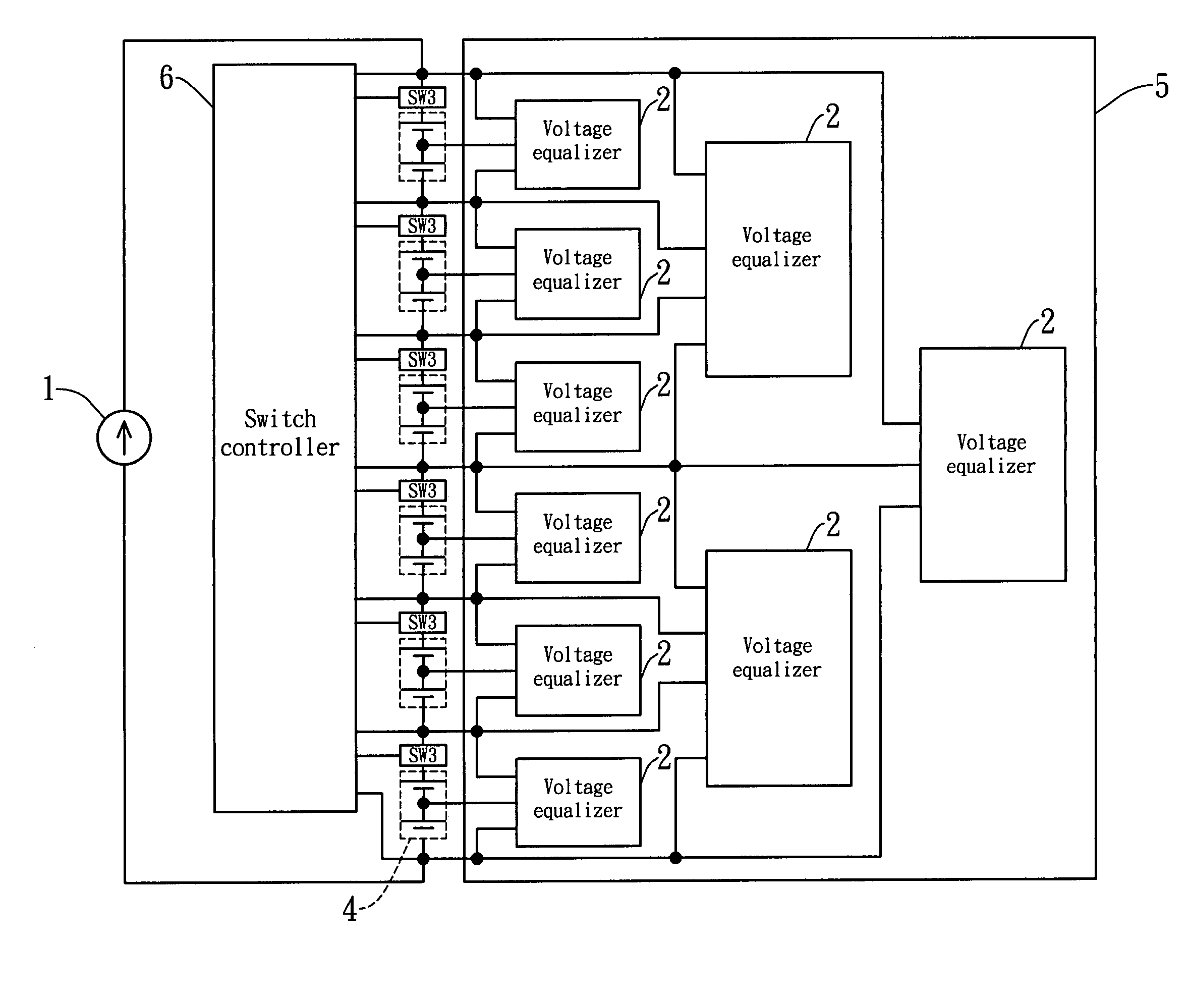
[0033]FIG. 5 shows a structural view of the hierarchical battery voltage equalization circuit of the present invention. The present invention provides a battery voltage-equalizing device, comprising a plurality of voltage equalizers, suitable for serially connected batteries having a great number of batteries therein. The voltage equalizers comprises a hierarchical structure 5, wherein the voltage equalizers 2 in the first layer (...


PUM


Abstract

This present invention provides a bridge battery voltage equalizer to equalize the voltages of the serially connected battery strings, comprising at least one battery crossing over an energy-transferring circuit. A plurality of the energy-transferring circuits are interconnected in a bridge architecture. Each energy-transferring circuit having four nodes comprises a first semiconductor switch, a first diode, a second semiconductor switch, a second diode, and an inductor. One end of the first element switch is connected to a negative pole of the first diode thereto. A positive pole of the second diode is connected to one end of the second element switch thereto. The inductor is an energy storing element that crosses over between the negative pole of the first diode and the positive pole of the second diode.

Description

FIELD OF THE INVENTION[0001]The present invention relates to a voltage equalizer for serially connected batteries, and more particularly, to a bridge battery voltage equalizer.BACKGROUND OF THE INVENTION[0002]Except a few low-voltage and low-power electronic apparatuses, the majority of batteries are connected in series in use, because the voltage of a single battery cell is not high enough, so its power loss is greater when it is used alone. For example, under the same load power, the voltage and capacity for a system of four batteries connected in series are four times as powerful as that of a single battery. However, the required output current is only one-fourth of that required for the single battery system. In this way, transmission loss is reduced by 16 times. Although there are advantages inherent in applying serially connected battery strings, practically speaking, its overall efficiency is less than expected, if the serially connected battery strings are only considered as...

Claims


Application Information

Patent Timeline
Patent Type & Authority Applications(United States)
IPC IPC(8): H02J7/00
CPCH02J7/0016
Inventor KONISHI, YOSHIHIROLUOR, TAIN-SYHHUANG, YI-SHUO
Owner IND TECH RES INST
Why Eureka
Try Eureka