
Method for mapping colors between imaging systems and method therefor

a color imaging and color mapping technology, applied in the field of color imaging, can solve the problems of inaccuracy of color conversion, undesirable color contamination, and difficulty in accurately color conversion of dark colors,

Inactive Publication Date: 2008-05-22
EDGE CHRISTOPHER J +2
View PDF65 Cites 12 Cited by
  • Summary
  • Abstract
  • Description
  • Claims
  • Application Information

AI Technical Summary

Benefits of technology

The technique achieves accurate and consistent color conversion by minimizing color errors and preserving black channel information, ensuring reliable color reproduction across different devices and conditions, while reducing computational and memory requirements.

Problems solved by technology

These techniques exhibit inaccurate color conversion between similar devices, potentially resulting in undesirable contamination of colors.
Furthermore, accurate color conversion of dark colors has often been particularly difficult because of inadequate processing of black channel data in many applications.
Because many devices are incapable of realizing the complete range of colors in a color space, gamut mapping typically involves compressing or scaling regions of the color space.
For many CMSs, gamut mapping is potentially inconsistent under certain circumstances, such as when using profiles generated by software from different vendors.
In addition, many CMSs exhibit inconsistencies when performing forward and reverse transformations between imaging systems.
Many CMS techniques exhibit other limitations in addition to the lack of accuracy in converting colors.
For example, many CMS techniques are relatively inflexible with respect to changes in illumination and observer conditions, gamut mapping, and choice of color space.
Certain techniques lack forward compatibility with future color standards.

Method used


Image

  • Method for mapping colors between imaging systems and method therefor
  • Method for mapping colors between imaging systems and method therefor
  • Method for mapping colors between imaging systems and method therefor

Examples


Embodiment Construction

[0016] The present invention is believed to be applicable to a variety of systems and arrangements that characterize color imaging systems. The invention has been found to be particularly advantageous for transforming colors between different color imaging systems. An appreciation of various aspects of the invention is best gained through a discussion of these particular application examples.

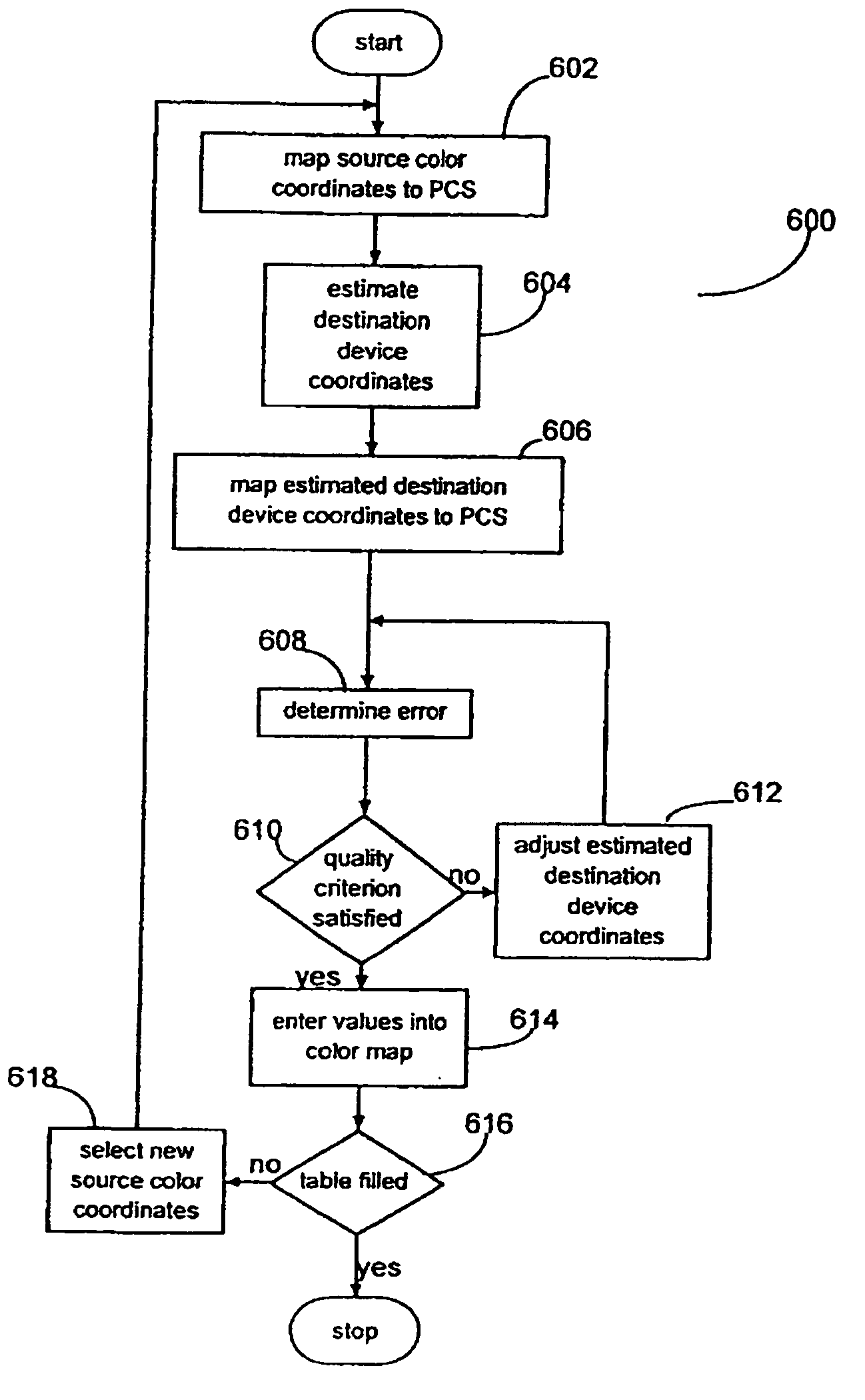
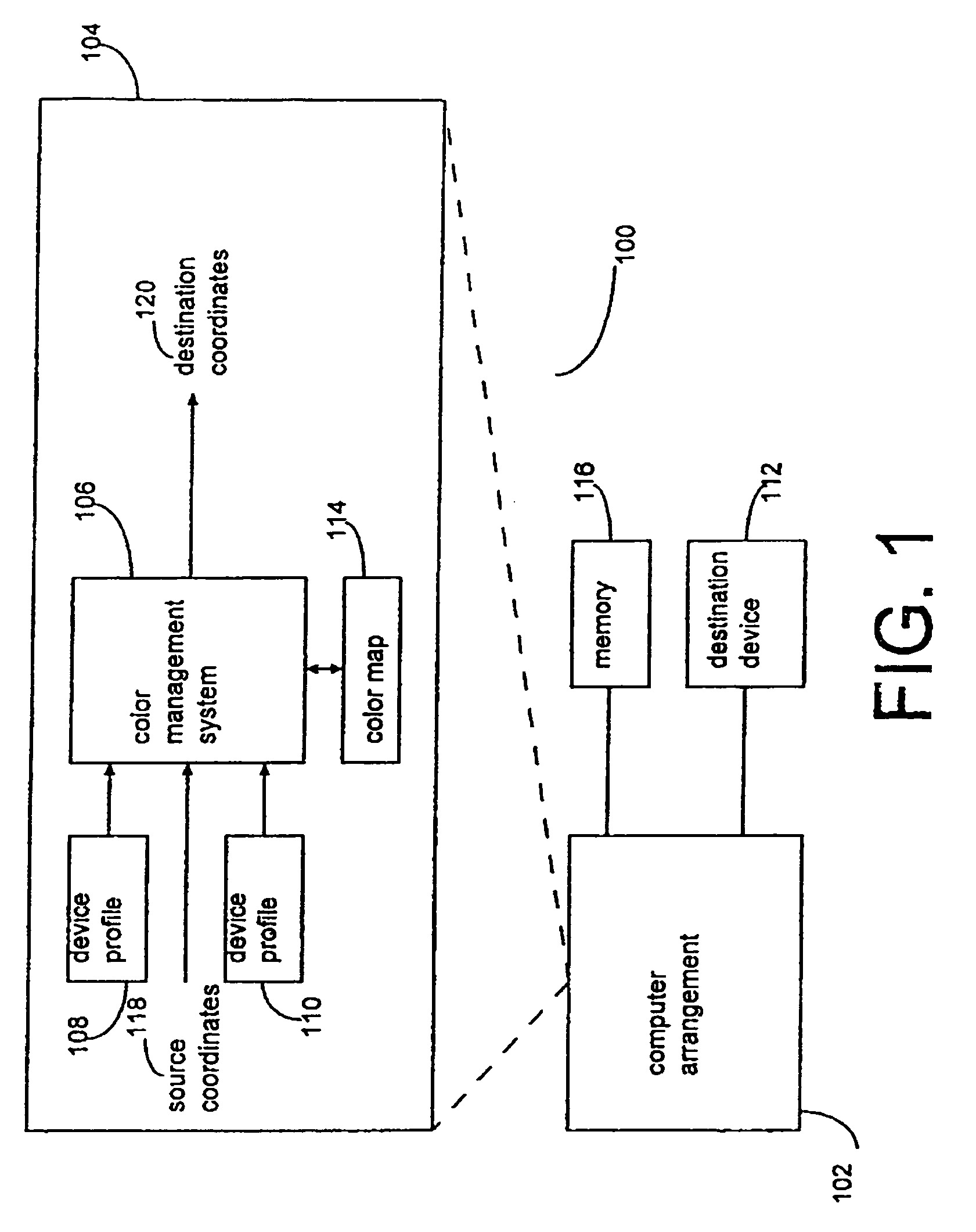
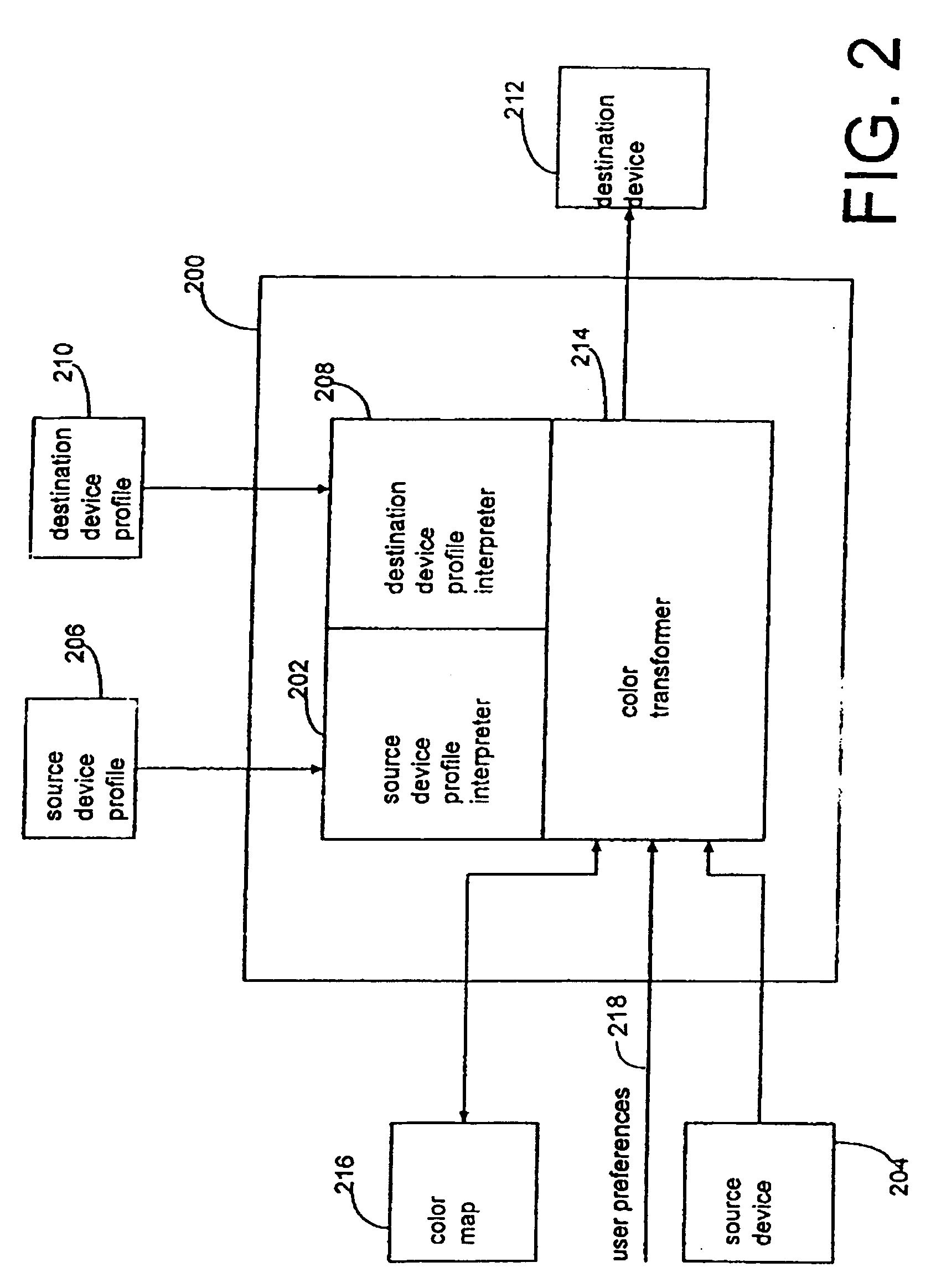
[0017] According to one aspect of the present invention, a color mapping technique may be applied to a variety of color imaging systems to generate a color map that can be used to transform the color response of one color imaging system, referred to as a source color imaging system, to match the color response of another color imaging system, referred to as a destination color imaging system. The color mapping technique projects color coordinates in the color space used by the source color imaging system into, for example, a device-independent color space. optimal color coordinates in the color...


PUM


Abstract

A method for performing color conversion includes configuring a color transformer to perform black point scaling when converting image data from a source device to a destination device. Another method for performing black point adjustment while performing color management conversions includes determining a device independent black reference vector for a device that corresponds to a predetermined set of device dependent values for that device. Converting the device dependent values to device independent data and adjusting the device independent data based on the device independent black reference vector.

Description

CROSS REFERENCE TO RELATED APPLICATIONS [0001] This application is a Divisional of U.S. application Ser. No. 09 / 536,366 filed Mar. 27, 2000, which is a Continuation of U.S. application Ser. No. 08 / 882,561 filed Jul. 3, 1997, now U.S. Pat. No. 6,088,038, and is a Continuation-In-Part of U.S. application Ser. No. 08 / 884,411 filed Jun. 27, 1997, now U.S. Pat. No. 6,108,442.FIELD OF THE INVENTION [0002] The present invention relates to color imaging. More particularly, the present invention relates to mapping colors between color imaging systems. BACKGROUND OF THE INVENTION [0003] Color reproduction processes typically involve using color imaging systems to produce colors on various media. These color imaging systems may be used to duplicate a color image from one medium to another medium, e.g., from one printed copy to another or from a display screen to a printed copy. Color reproduction processes are used in various application environments, for example, color proofing applications. ...

Claims


Application Information

Patent Timeline
Patent Type & Authority Applications(United States)
IPC IPC(8): G09G5/02H04N1/60
CPCG09G5/02H04N1/6052H04N1/603H04N1/407
Inventor EDGE, CHRISTOPHER J.FISCHER, TIMOTHY A.ROZZI, WILLIAM A.
Owner EDGE CHRISTOPHER J
Learn More