Bifeed serpentine cooled blade

a blade cooling and serpentine technology, applied in the field of turbine blade cooling, can solve the problems of blade cooling configuration complexity, undesirable airfoil cracking, and engine efficiency reduction

Active Publication Date: 2008-05-22
GENERAL ELECTRIC CO
View PDF19 Cites 48 Cited by
  • Summary
  • Abstract
  • Description
  • Claims
  • Application Information

AI Technical Summary

Problems solved by technology

The cooling air bled from the compressor bypasses the combustor and correspondingly reduces efficiency of the engine.
The complexity of blade cooling configurations is also based on the varying distribution of pressure and heat loads around the concave pressure side of the airfoil and the convex suction side which extend radially in span from root to tip and axially in chord between opposite leading and trailing edges.
The life of the typical turbine blade is limited by any local hot spot experienced thereby which increases the thermal distress experienced by the blade eventually leading to undesirable airfoil cracking for example.
The airfoil has relatively thin walls, and any thermal crack developed therein during operation can lead to undesirable leakage of the internal cooling air.
Airfoil cracking due to thermal distress typically occurs at the airfoil tip which is subject to heating by the combustion gases not only from the opposite pressure and suction sides of the airfoil, but also from combustion gases leaking over the tip in the small radial clearance or gap provided with the surrounding turbine shroud.

Method used


Image

  • Bifeed serpentine cooled blade
  • Bifeed serpentine cooled blade
  • Bifeed serpentine cooled blade

Examples


Embodiment Construction

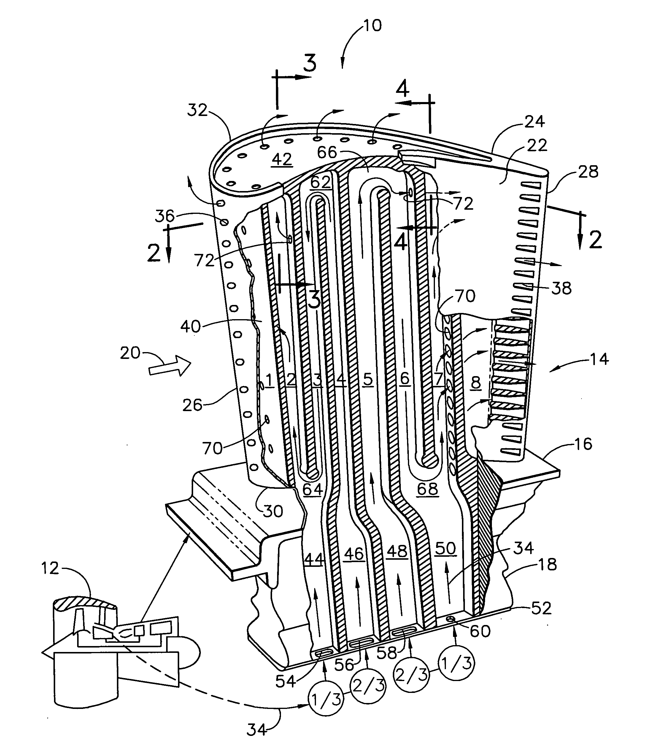
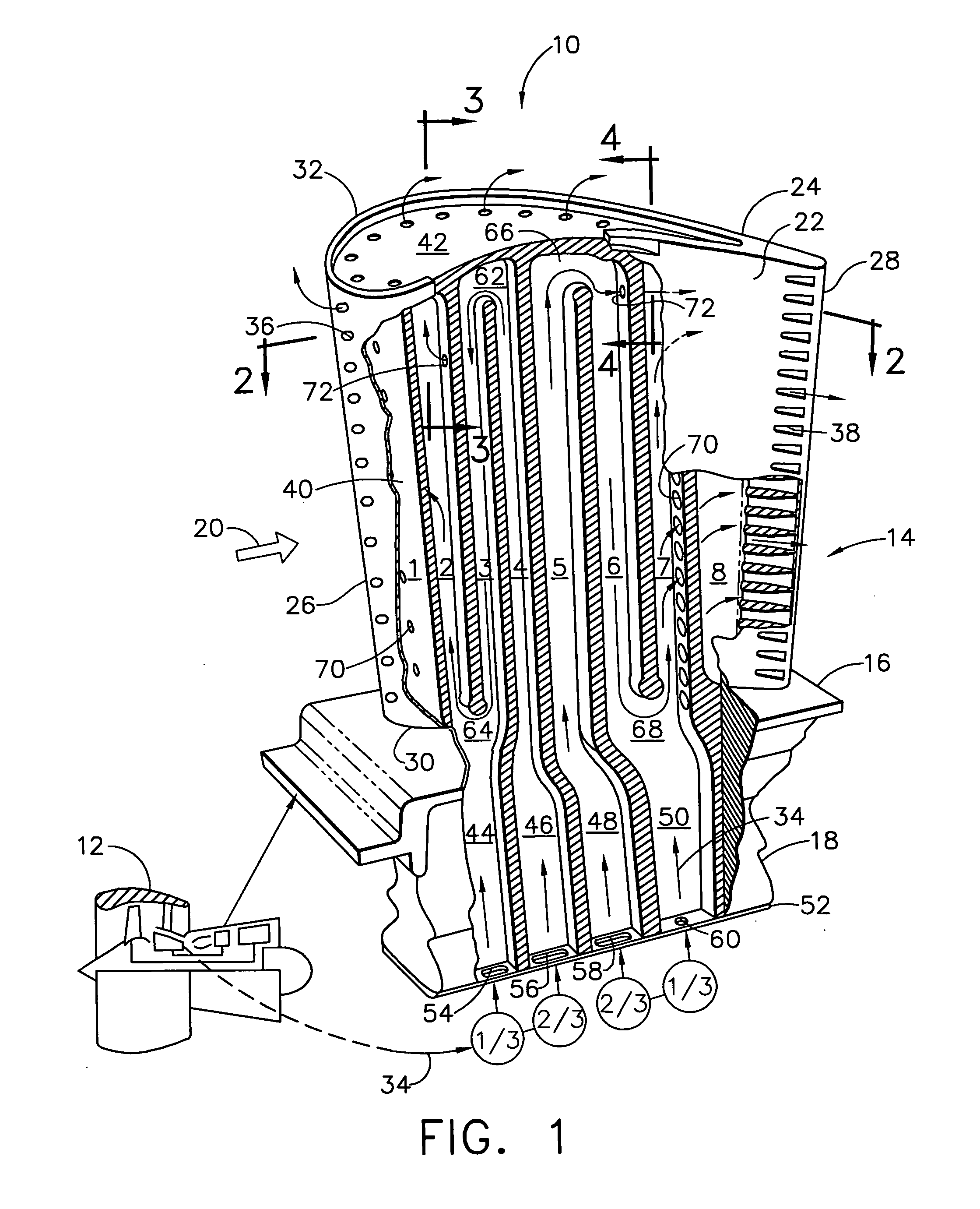
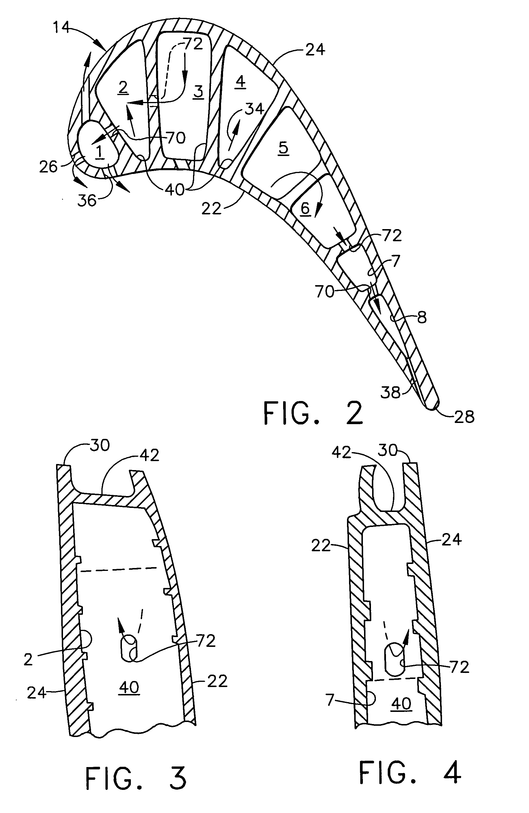
[0018]FIG. 1 illustrates an exemplary first stage turbine rotor blade 10 for use in the HPT of a gas turbine engine 12. The blade is typically cast from superalloy metal with an airfoil 14, platform 16 at the root thereof, and a supporting dovetail 18 in an integral, one-piece assembly.

[0019]The dovetail 18 may have any conventional form, such as the axial-entry dovetail illustrated, which mounts the blade in a corresponding dovetail slot in the perimeter of a supporting rotor disk (not shown). The disk holds a full row of the blades spaced circumferentially apart from each other to define inter-blade flow passages therebetween.

[0020]During operation, combustion gases 20 are generated in the combustor of the engine and suitably channeled downstream over the corresponding turbine blades 10 which extract energy therefrom for powering the supporting rotor disk. The individual platform 16 provides a radially inner boundary for the combustion gases and adjoins adjacent platforms in the f...


PUM


Abstract

A turbine blade includes forward and aft serpentine cooling circuits terminating in corresponding forward and aft impingement channels. Each serpentine circuit has two metered inlets for distributing primary inlet flow to the first passes thereof and supplemental inlet flow to the last passes thereof.

Description

[0001]The U.S. Government may have certain rights in this invention pursuant to contract number N00019-03-C-0361 awarded by the U.S. Department of the Navy.BACKGROUND OF THE INVENTION[0002]The present invention relates generally to gas turbine engines, and, more specifically, to turbine blade cooling.[0003]In a gas turbine engine, air is pressurized in a compressor and mixed with fuel in a combustor for generating hot combustion gases. Energy is extracted from the gases in high and low pressure turbines which power the compressor and a fan in an exemplary turbofan aircraft engine configuration.[0004]The first stage turbine rotor blades receive hot combustion gases from their corresponding turbine nozzle directly from the combustor. The turbine blades are therefore made of superalloy metal having enhanced strength at the high operating temperature of the turbine. And, the blades are typically hollow and internally cooled by bleeding a portion of pressurized air from the compressor.[0...

Claims


Application Information

Patent Timeline
Patent Type & Authority Applications(United States)
IPC IPC(8): F01D5/18F01D5/00F28D15/00F01D17/00
CPCF01D5/187Y02T50/676Y02T50/673Y02T50/671Y02T50/60
Inventor CORREIA, VICTOR HUGO SILVAMANNING, ROBERT FRANCISREDDY, BHANU MAHASAMUDRAM
Owner GENERAL ELECTRIC CO
Why Eureka
Try Eureka