Metal wood club

a golf club and metal wood technology, applied in the field of golf clubs, can solve the problems of undetectable, undetectable, undetectable hooking or slicing, and the influence of known methods on the effect of face angle, and achieve the effect of reducing the change of face angl

Inactive Publication Date: 2008-05-22
ACUSHNET CO
View PDF11 Cites 64 Cited by
  • Summary
  • Abstract
  • Description
  • Claims
  • Application Information

AI Technical Summary

Benefits of technology

[0012]The present invention is directed to an improved weighting system for wood-type and hybrid golf clubs that allows customization of mass characteristics. In addition, the present i

Problems solved by technology

In addition, due to difficulties in manufacturing one-piece club heads to high dimensional tolerances, the use of multi-piece constructions allows the manufacture of a club head to a tight set of standards.
However, these environmental effects are beyond the control of the golf equipment manufacturer.
The known methods, however, often fail to produce predictable results due to inaccurate and inconsistent measuring of baseli

Method used


Image

  • Metal wood club
  • Metal wood club
  • Metal wood club

Examples


first embodiment

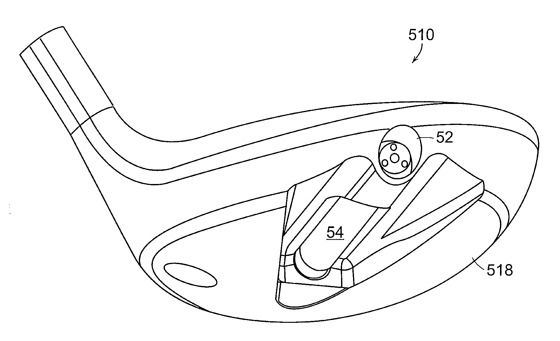
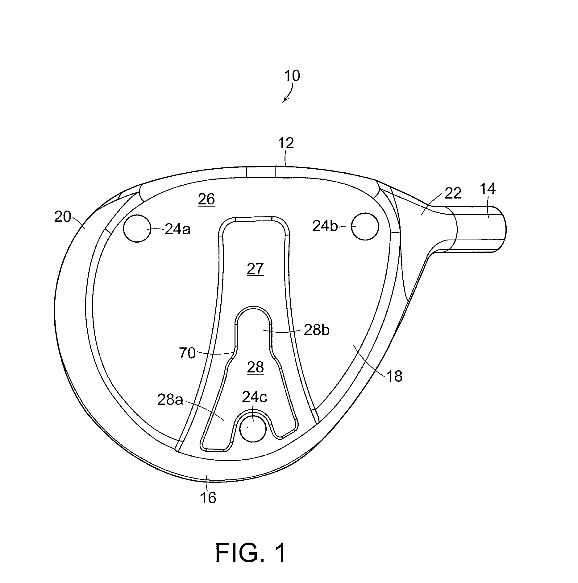
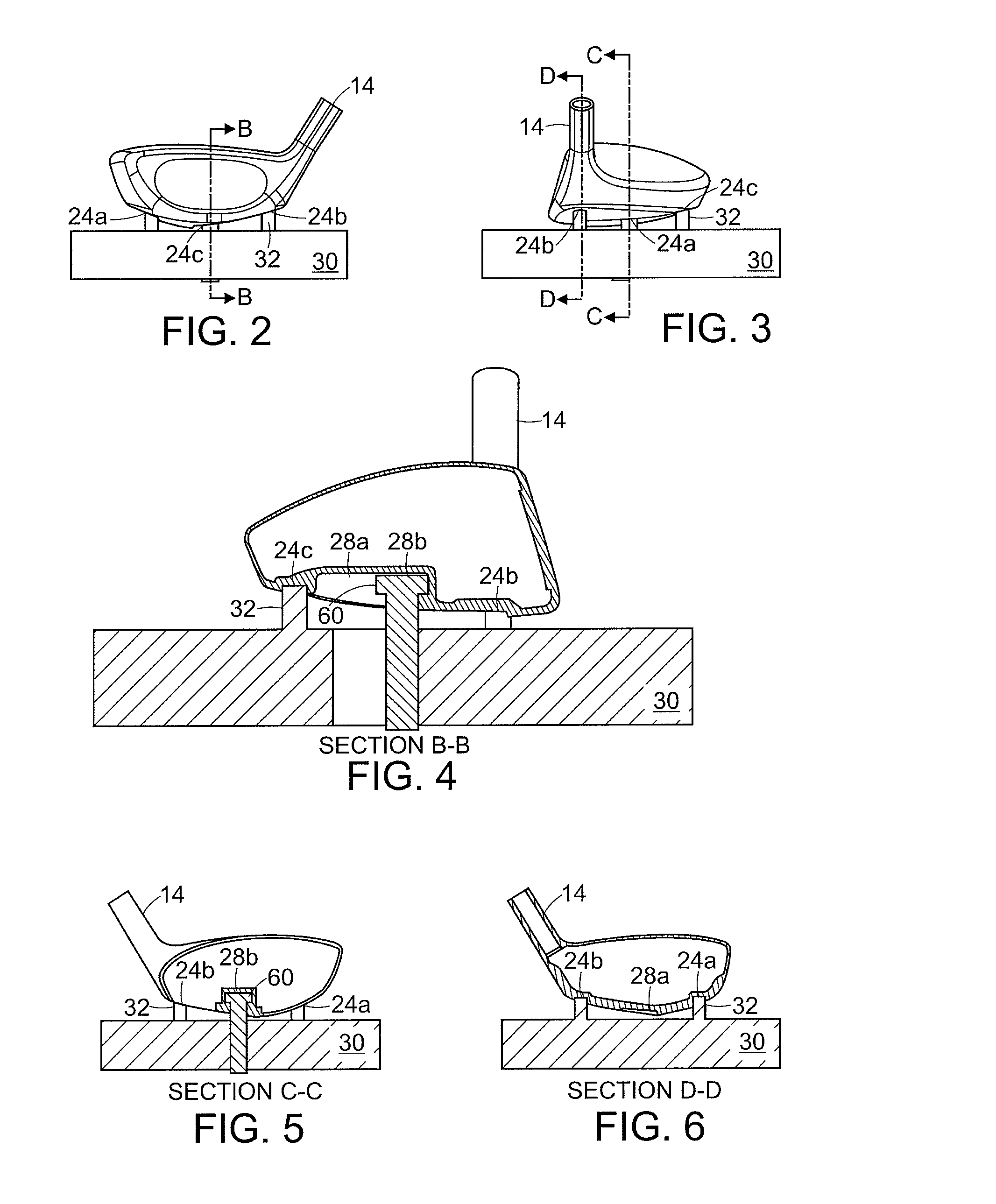
[0044]In the present invention, as illustrated in FIG. 1, golf club head 10 has hitting face 12, hosel 14, back 16, sole 18 and skirt 20. Sole 18 includes three attachment points 24a, 24b and 24c. As shown in FIGS. 2-6, attachment points 24a, 24b and 24c correspond to three posts 32 on tool 30. An example of tool 30 is shown in more detail in FIGS. 7 and 8 and is preferably a machine for bending the hosels of golf club heads and thereby modifying the lie and loft angles of golf club heads. According to this embodiment, a first attachment point 24a is located on sole 18 adjacent to hitting face 12 and toward toe 20, a second attachment point 24b is located on sole 18 adjacent to hitting face 12 and toward heel 22, and a third attachment point 24c is located toward back 16 of sole 18, roughly aligned with the center of hitting face 12. This configuration of three attachment points optimizes the stability of club head 10 as it rests on posts 32, as three is the minimum number of points...

second embodiment

[0053]According to another aspect of the present invention and shown in FIG. 12, contact area 40 is located on sole 18 on or parallel to the X-Y plane that includes the point M at the top of grip 65 and the center of gravity of club 50, called point N. Contact area 40 may be on the line that includes M and N or may be toe-ward of the intersection of said line with sole 18. Preferably, contact area 40 is located closer to the toe of club head 10, and contact area 40 can be a contact area. This position helps to stabilize club 50 when it is supported by the hands of the golfer and is at rest in address position, as the center of gravity then behaves in a way similar to a ballast a of ship—it prevents the club from tipping or wobbling in the hands of the golfer.

[0054]In an alternative embodiment of this aspect of the current invention, shown in FIGS. 13-17, sole 118 of club head 110 includes contact area 140, comprising a sphere segment. Preferably, sphere segment 140 is located closer...

fourth embodiment

[0056]the present invention is depicted in FIG. 18 and presents sole 218 of golf club head 210, wherein pads 46a, 46b, 46c and 46d and pad 48 are incorporated into sole 218. Pads 46a-d and pad 240 are composed of material that may be milled, polished, shaved or otherwise extracted after initial manufacture of golf club head 210 in order to vary the relief of sole 218 and to adjust mass characteristics of club head 210. According to an aspect of this embodiment, pads 46a-d and pad 240 may be made of aluminum, stainless steel, carbon steel, titanium, titanium alloy, or other metals or composites. Preferably, pad 46a is located toward toe 220 and roughly centered between the edge of hitting face 212 and tailing edge 216. Pad 46b is preferably located adjacent to the edge of hitting face 212 and roughly centered between toe 220 and heel 222. Pad 46c is preferably located toward heel 222 and roughly centered between the edge of hitting face 212 and tailing edge 216. Pad 46d is preferably...


PUM


Abstract

In one embodiment, a golf club head is presented having a sole with three recessed cavities for attachment to a hosel-bending tool. In another embodiment, a golf club head is presented having a sole that includes one predetermined contact area proximal to the toe edge of the sole. In another embodiment, a golf club head is presented having a sole in which pads of material are incorporated that may be milled to vary the relief of the sole and to modify mass characteristics of the club head. Yet another embodiment presents a golf club head having a body with a cavity to receive a cartridge that has a constant density and weight.

Description

RELATED APPLICATIONS[0001]This application is a continuation-in-part of U.S. application Ser. No. 11 / 560,905, filed on Nov. 17, 2006, which is incorporated by reference herein in its entirety.FIELD OF THE INVENTION[0002]The present invention relates to an improved golf club. More particularly, the present invention relates to a wood-type golf club head with improved physical attributes.BACKGROUND[0003]Golf club heads come in many different forms and makes, such as wood- or metal-type (including drivers and fairway woods), iron-type (including wedge-type club heads), utility- or specialty-type, and putter-type. Each of these styles has a prescribed function and make-up. The present invention relates primarily to hollow golf club heads, such as wood-type and utility-type (generally referred to herein as wood-type golf clubs).[0004]Wood-type or metal-type golf club heads generally include a front or striking face, a crown, a sole and an arcuate skirt including a heel, a toe and a back....

Claims


Application Information

Patent Timeline
IPC IPC(8): A63B53/04
CPCA63B53/02A63B2053/045A63B53/06A63B59/0074A63B2053/022A63B2053/0408A63B2053/0412A63B2053/0416A63B2053/0433A63B2053/0458A63B2053/0491G01B5/0023G01B5/24A63B2209/00A63B53/0466A63B60/42A63B60/02A63B60/52A63B53/022A63B53/0412A63B53/0458A63B53/0408A63B53/0416A63B53/0433A63B60/00A63B53/04A63B53/045
Inventor BENNETT, THOMAS ORRINBURNETT, MICHAEL SCOTTHARVELL, CHRISTOPHER D.MURPHY, STEPHEN S.
Owner ACUSHNET CO
Why Eureka
Try Eureka