
Signal message decompressor

a decompression and signal technology, applied in the field of data compression methods, can solve problems such as significant transmission delays, limited static dictionary use, and adverse effects on call setup and feature invocation

Inactive Publication Date: 2008-05-22
NOKIA CORP
View PDF18 Cites 20 Cited by
  • Summary
  • Abstract
  • Description
  • Claims
  • Application Information

AI Technical Summary

Benefits of technology

[0020]Embodiments of the invention as described above have the advantage that the compressor is able to provide an indicator where the indicator value can assist in the selection of a specific dictionary in any decompression operation. Thus the decompression operation can be optimised to use specific dictionaries allowing faster decompression or requiring less process memory as only indicated dictionaries are required to be used in the decompression procedure.
[0024]Therefore embodiments of the invention described above may be further optimised so that the compression operation selects only dictionaries indicated to be present in a potential decompression device carrying out a decompression process. Thus in any embodiments of the above, there are fewer compression-decompression cycle errors where the compression process uses a dictionary not found by the decompression process.
[0026]Thus embodiments of the invention described above may be further optimised so that the compression operation selects only algorithms indicated to be present in a potential decompression device carrying out a decompression process. Thus in any embodiments of the above there are fewer compression-decompression cycle errors where the compression process uses a compression algorithm not found by the decompression process.

Problems solved by technology

With low-rate IP connectivity, transmission delays are significant.
Call setup and feature invocation are adversely affected by retransmissions and multiple messaging, as required in some flows.
However static dictionary use is limited and problematic as they have to be synchronized between compressor and decompressor.
This approach is inefficient as it requires signalling overhead between the compressor and decompressor or between compressor / decompressor and central static dictionary store in order to maintain synchronisation of dictionaries.
This solution however has problems in that in the standard static dictionary is typically either small and quick to use (i.e. can only produce a limited compression ratio) or is large and slow (i.e. the compression benefit is large but so is the computational and speed cost).

Method used


Image

  • Signal message decompressor
  • Signal message decompressor
  • Signal message decompressor

Examples


Embodiment Construction

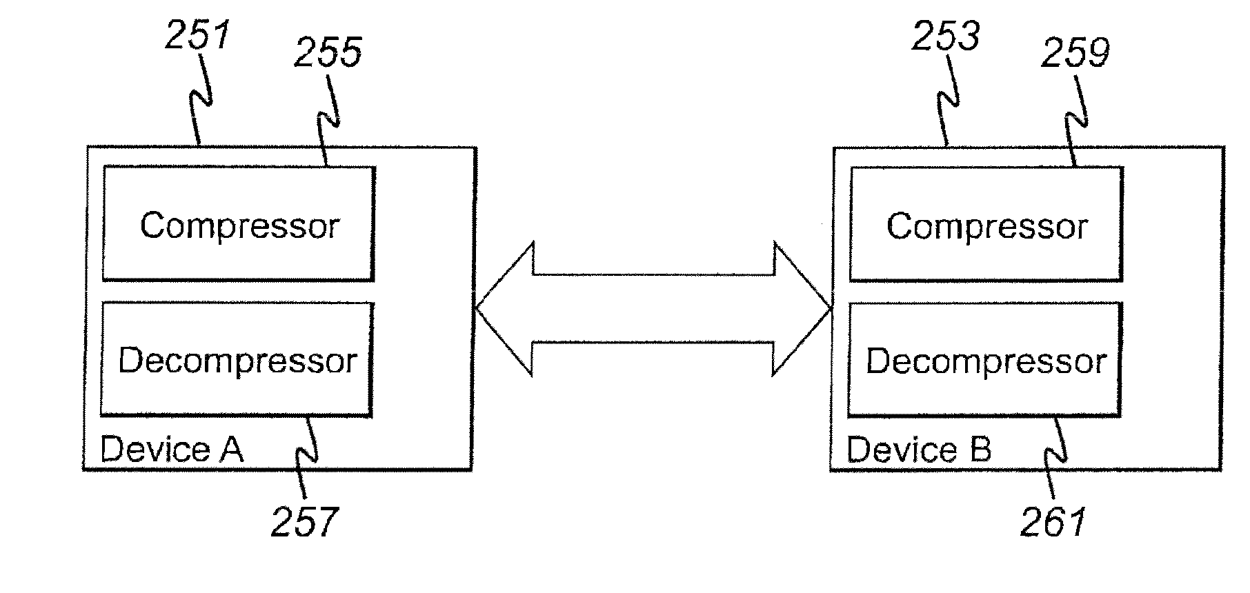
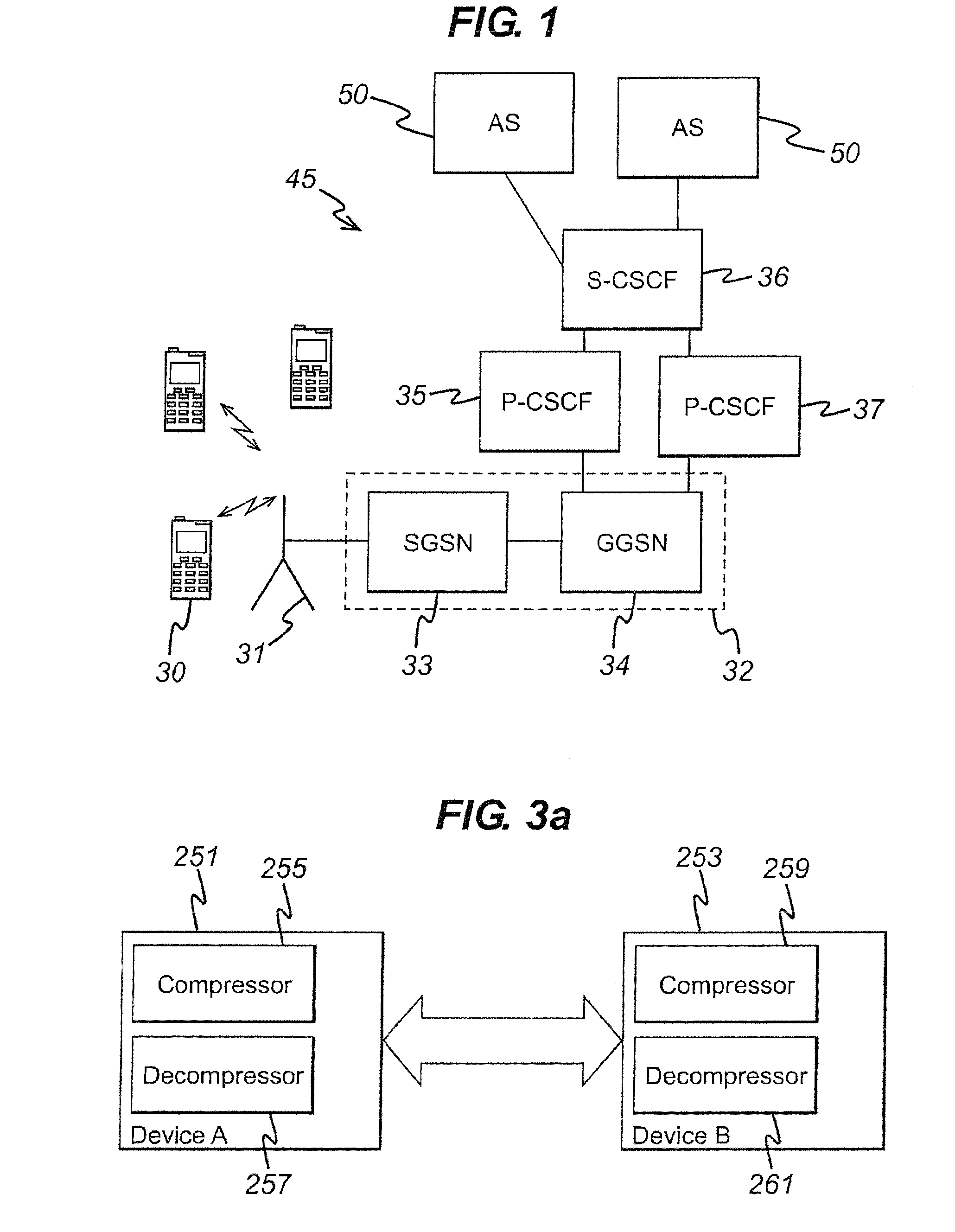
[0062]Certain embodiments of the present invention will be described in the following by way of example, with reference to the exemplifying architecture of a third generation (3G) mobile communications system. However, it shall be appreciated that the embodiments may be applied to any suitable communication system. Furthermore although the examples as described below refer to a compression operation and specifically to a DEFLATE algorithm variant of a SigComp compression algorithm, it shall be appreciated that the embodiments may be applied to any suitable compression / decompression algorithm where static dictionaries can be used.

[0063]Reference is made to FIG. 1 which shows an example of a network architecture wherein embodiments of the invention may be embodied. In FIG. 1 an IP Multimedia Network 45 is provided for offering IP multimedia services for IP Multimedia Network subscribers.

[0064]As described above, access to IP Multimedia (IM) services can be provided by a mobile communi...


PUM


Abstract

A method for compressing data comprising, selecting a dictionary, compressing data using the dictionary, and appending an indicator to the compressed data, wherein the indicator comprises an indicator value representing the dictionary. A compression algorithm may also be defined, wherein the compressing of data comprises compressing data using the selected compression algorithm and dictionary, and wherein the first indicator further comprises a second indicator value representing the compression algorithm.

Description

FIELD OF THE INVENTION[0001]The present invention relates to a method for compressing data, and in particular, a method for compressing data in signal messages within communication sessions.BACKGROUND OF THE INVENTION[0002]This section is intended to provide a background or context to the invention that is recited in the claims. The description herein may include concepts that could be pursued, but are not necessarily ones that have been previously conceived or pursued. Therefore, unless otherwise indicated herein, what is described in this section is not prior art to the description and claims in this application and is not admitted to be prior art by inclusion in this section.[0003]A communication system can be seen as a facility that enables communication sessions between two or more entities such as user equipment and / or other nodes associated with the communication system. The communication may comprise, for example, communication of voice, data, multimedia and so on. A user eq...

Claims


Application Information

Patent Timeline
Patent Type & Authority Applications(United States)
IPC IPC(8): G06F17/00
CPCH03M7/30H04L65/1016H04W80/10H04W28/06
Inventor IONESCU, CATALINMOSTAFA, MIRAJ
Owner NOKIA CORP
Learn More