Substrate processing apparatus and substrate processing method

a processing apparatus and substrate technology, applied in the direction of cleaning process and apparatus, chemistry apparatus and processes, cleaning using liquids, etc., can solve the problems of excessive volume, damage to the substrate, destruction of patterns or otherwise, etc., and achieve the effect of preventing damage to the substrate and facilitating particle removal

Inactive Publication Date: 2008-05-29
DAINIPPON SCREEN MTG CO LTD
View PDF7 Cites 25 Cited by
  • Summary
  • Abstract
  • Description
  • Claims
  • Application Information

AI Technical Summary

Benefits of technology

[0009]The present invention has been made in light of the problems above, and accordingly aims at providing a substrate processing apparatus and a substrate processing method with which it is possible to facilitate particle removal while preventing damage upon a substrate.

Problems solved by technology

By the way, an attempt to increase the pressure which develops due to volume expansion upon freezing of the liquid film and accordingly facilitate removal of the particles, the pressure may become excessively large and lead to destruction of patterns or otherwise damage the substrate.
However, the apparatus described in JP-A-3-145130 does not provide sufficient consideration on these.

Method used


Image

  • Substrate processing apparatus and substrate processing method
  • Substrate processing apparatus and substrate processing method
  • Substrate processing apparatus and substrate processing method

Examples


first embodiment

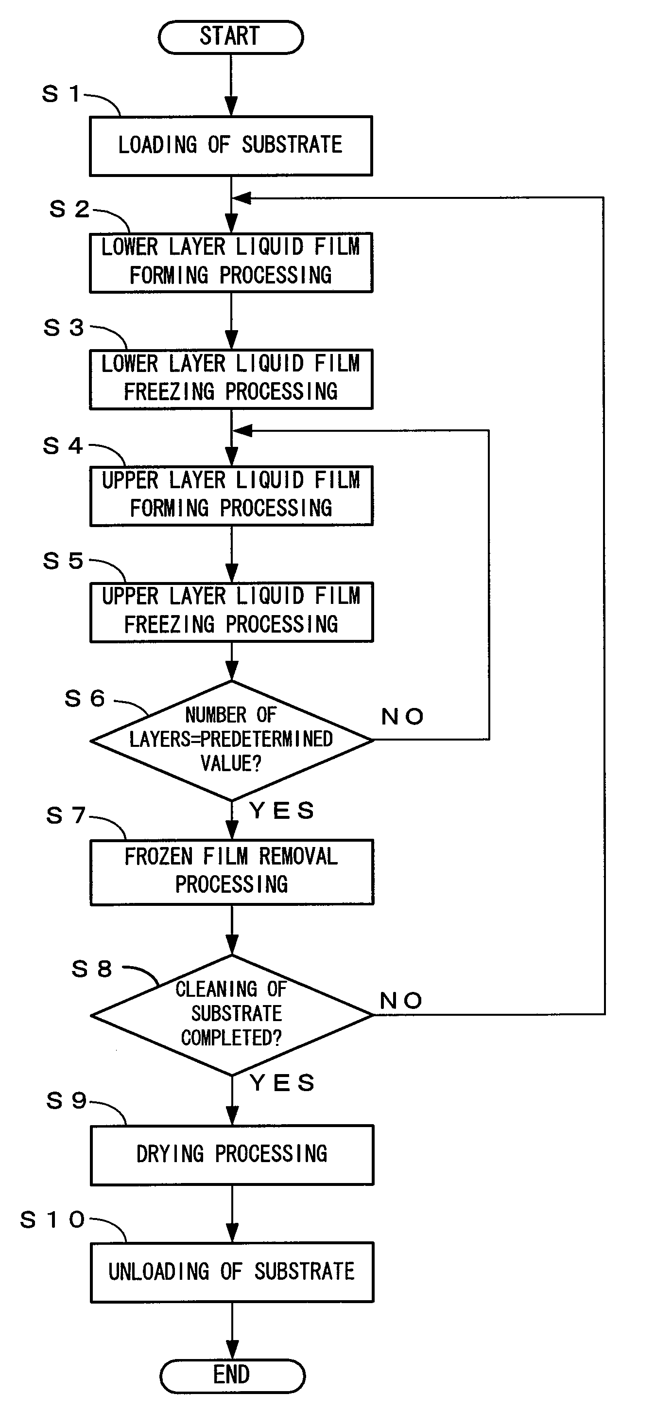
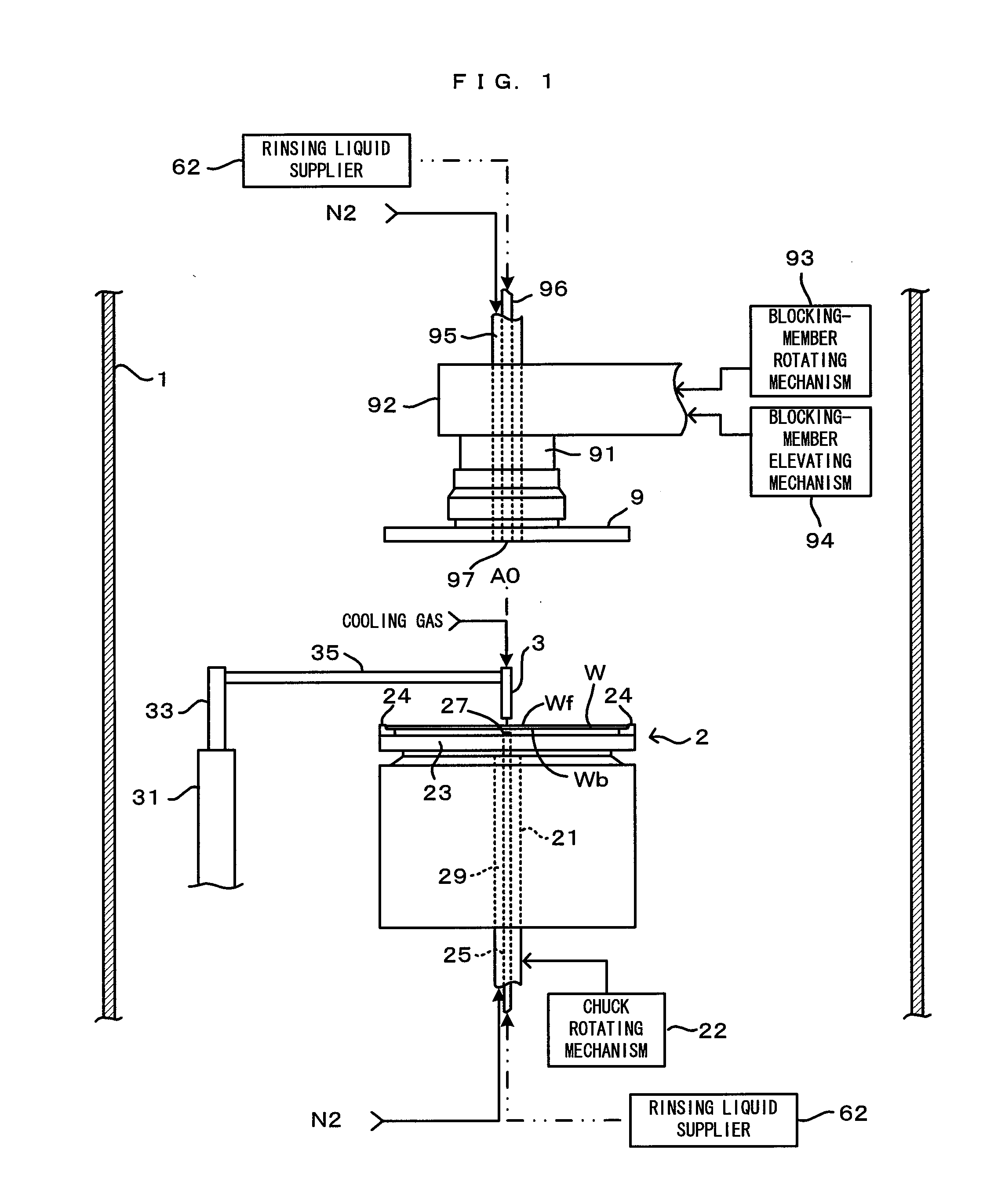
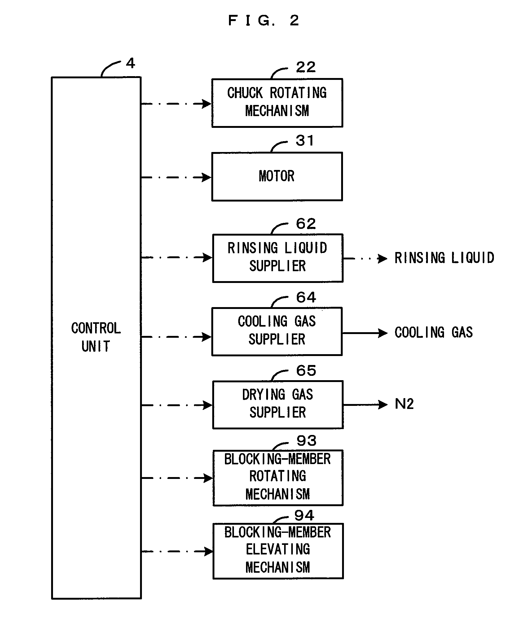
[0031]FIG. 1 is a diagram showing a substrate processing apparatus of a first embodiment of the invention. FIG. 2 is a block diagram showing a control construction of the substrate processing apparatus shown in FIG. 1. This substrate processing apparatus is a single wafer type substrate processing apparatus that is used for the cleaning processes for the purpose of removing contaminants such as particles adhering to a top surface Wf and a rear surface Wb of a substrate W such as semiconductor wafer. More specifically, this substrate processing apparatus is an apparatus which forms a liquid film on the top surface Wf of the substrate W, forms a lower layer frozen film by freezing the liquid film, then forms an upper layer frozen film on the top surface of the lower layer frozen film in a layered structure, and then, removes whole of the frozen film from the top surface Wf of the substrate W, whereby a cleaning processing is performed to the substrate W.

[0032]This substrate processing...

second embodiment

[0085]FIG. 8 is a diagram showing a second embodiment of a substrate processing apparatus according to the invention, and FIG. 9 is a block diagram which shows the control structure of the substrate processing apparatus of FIG. 8. The second embodiment is quite different from the first embodiment in that DIW is supplied as a mist-generating nozzle 7 discharges minute droplets toward the surface of the lower layer frozen film 13f for the purpose of forming the upper layer frozen film, and the rinsing liquid supplier 62 is replaced with a rinsing liquid supplier 620. The rinsing liquid supplier 620 is different from the rinsing liquid supplier 62 only in that it does not comprise the temperature adjuster, but is otherwise identical in structure to the rinsing liquid supplier 62. That is, DIW supplied to the substrate W from the rinsing liquid supplier 620 for the purpose of forming the lower layer liquid film is not cooled but is at room temperature. The same parts as those of the fir...


PUM


Abstract

DIW is supplied toward a surface of a substrate to form a lower layer liquid film, which is then frozen to form a lower layer frozen film. Further, DIW cooled down to a temperature at which the lower layer frozen film will not melt is supplied toward a surface of the lower layer frozen film to form an upper layer liquid film, which is then frozen to form an upper layer frozen film in a layered structure. DIW which is at room temperature is thereafter supplied, thereby melting the entirety of the lower layer frozen film and the upper layer frozen film to remove these films together with particles off from the surface of the substrate.

Description

CROSS REFERENCE TO RELATED APPLICATION[0001]The disclosure of Japanese Patent Application No. 2006-320443 filed Nov. 28, 2006 including specification, drawings and claims is incorporated herein by reference in its entirety.BACKGROUND OF THE INVENTION[0002]1. Field of the Invention[0003]The present invention relates to a substrate processing apparatus and a substrate processing method which freeze a liquid film formed on a surface of a substrate and removes the frozen film, the substrate including various types such as semiconductor wafers, glass substrates for photomask, glass substrates for liquid crystal display, glass substrates for plasma display, substrates for FED (field emission display), substrates for optical disks, substrates for magnetic disks, and substrates for magnet-optical disks (hereinafter called simply a “substrate”).[0004]2. Description of the Related Art[0005]Conventionally used is a technique of freezing a liquid film as it is maintained adhering to a substrate...

Claims


Application Information

Patent Timeline
Patent Type & Authority Applications(United States)
IPC IPC(8): B08B3/00
CPCB08B3/10H01L21/6715H01L21/67051B08B7/0092
Inventor MIYA, KATSUHIKO
Owner DAINIPPON SCREEN MTG CO LTD
Why Eureka
Try Eureka