Component especially for horology with surface topology and method for manufacturing the same

Active Publication Date: 2020-02-13
NIVAROX FAR
View PDF4 Cites 0 Cited by
  • Summary
  • Abstract
  • Description
  • Claims
  • Application Information

AI Technical Summary

Benefits of technology

[0003]It is an object of the present invention to overcome the aforecited drawbacks by proposing a system with two components in friction contact wherein at least one component has a topolog

Problems solved by technology

This scalloping is an inherent defect of the process that those skil

Method used


Image

  • Component especially for horology with surface topology and method for manufacturing the same
  • Component especially for horology with surface topology and method for manufacturing the same

Examples


Embodiment Construction

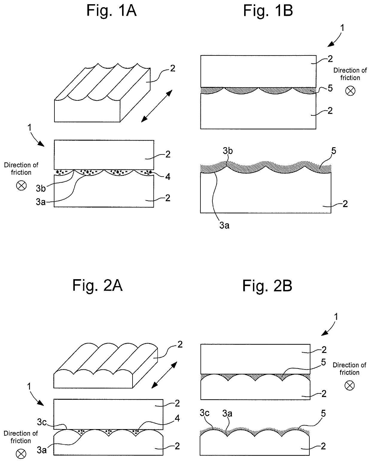
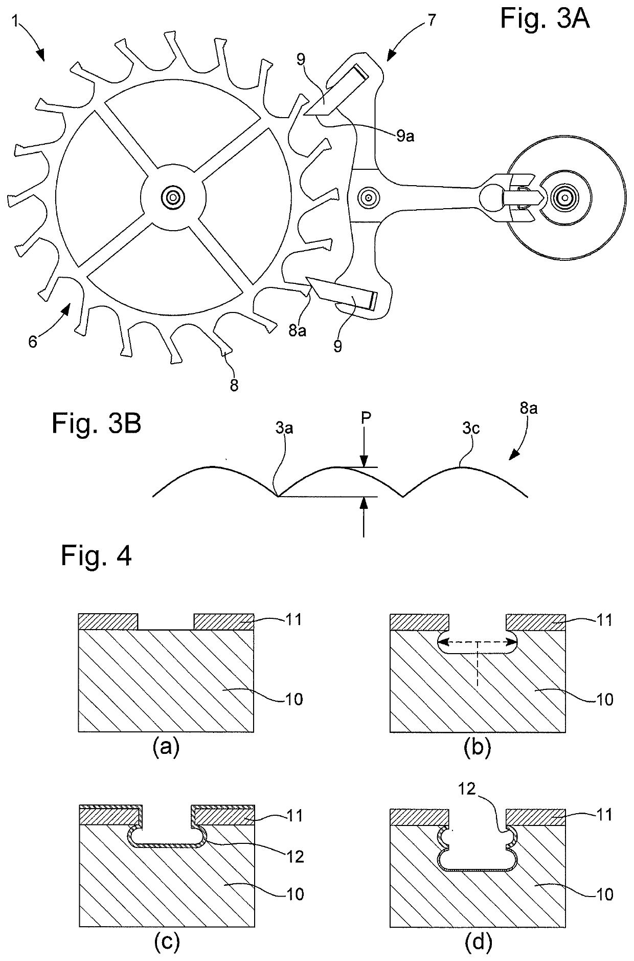
[0022]The present invention relates to components made from metal or from silicon comprising surfaces intended to be subjected to friction during use. The present invention thus relates more specifically to a system including two components having surfaces subjected to friction in a so-called ‘functional’ area. In the field of horology, this may be, for example, a system of the following type: escape wheel / pallets, cam / sensor, click / toothed wheel, jumper / disc, coupling disc / spring, brake disc / brake lever, etc. The present invention also relates to the moulds that make it possible to produce these components by electroforming. It also relates to the method for manufacturing the components or moulds.

[0023]As represented schematically in FIGS. 1A-2B, at least one of the two components 2 of system 1 has, in the functional area of its friction surface, a surface topology that, on the one hand, facilitates the evacuation of third-body particles and, on the other hand, forms a reservoir fo...


PUM

PropertyMeasurementUnit
Depthaaaaaaaaaa
Depthaaaaaaaaaa
Depthaaaaaaaaaa

Abstract

A system including two components intended to be in friction contact with each other in a given direction, wherein the friction occurs in a functional area, wherein the system is at least one of the two components including, on a surface in the functional area, a texture formed of a series of troughs of rounded shape separated by peaks or a series of bumps of rounded shape separated by troughs, the troughs extending parallel in the given direction and allowing for the evacuation of debris produced by friction and serving as a reservoir for a lubricant. A method for manufacturing at least one component or a mold by the DRIE (deep reactive ion etching) process, wherein surface defects on the sidewalls machined by the DRIE process are used to form the troughs.

Description

FIELD OF THE INVENTION[0001]The present invention relates to a micromechanical component, used, in particular, in the field of horology, intended to be subjected during use to friction contact with another component. It also relates to the method for manufacturing the component.PRIOR ART[0002]Numerous timepiece components, such as escapement components, jumpers, springs, etc., are subjected to friction during use. Conventionally, to be well made, such components must have a contact / friction surface that is perfectly smooth. However, friction between two bodies generally causes the formation of wear particles forming a third body. Far from having a proven positive effect, this third body may cause accelerated wear of the component with a detrimental effect on its function. To prevent such wear and reduce the friction forces that result in losses for certain functions, lubrication is applied to the surfaces of the components that come into friction contact. However, in the configurati...

Claims


Application Information

Patent Timeline
IPC IPC(8): B81C1/00G04B13/02
CPCB81C2201/0132B81C1/00619G04B13/027G04B13/026B81C1/00103B81C1/00031B81B5/00B81B2201/035B81C99/0075B81C99/0085B81C2201/115G04D3/0069G04B13/022G04B15/14G04B31/08B81B3/0005B81B3/001B81B2203/0384G04B13/02G04B31/06
Inventor GANDELHMAN, ALEXCUSIN, PIERREVERARDO, MARCO
Owner NIVAROX FAR
Why Eureka
Try Eureka