Heat dissipation device

Inactive Publication Date: 2008-05-29
HON HAI PRECISION IND CO LTD +1
View PDF11 Cites 27 Cited by
  • Summary
  • Abstract
  • Description
  • Claims
  • Application Information

AI Technical Summary

Benefits of technology

[0007]A heat dissipation device includes a base including a base plate made of a first metal and a substrate made of a second metal. The second metal has a lower heat conductivity and a lower cost than those of the first metal. The substrate comprises a frame with a window receiving the base plate therein and an engaging plate spanning over the window. A fin set includes a plurality of fins parallel with and spaced from each other. A heat pipe has an evaporating section thermally s

Problems solved by technology

If the heat is not dissipated duly, the stability of the operation of the electronic devices will be impacted severely.
However, the heat dissipating efficiency of the heat dissipation device is determined mostly by heat conductivity of the based; as a result, the base made of a material having comparatively low conductivity such as aluminum unduly affec

Method used


Image

  • Heat dissipation device
  • Heat dissipation device
  • Heat dissipation device

Examples


Example

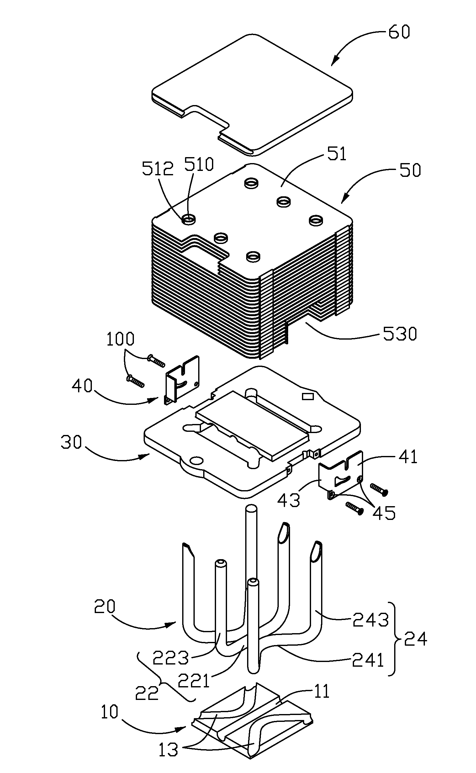
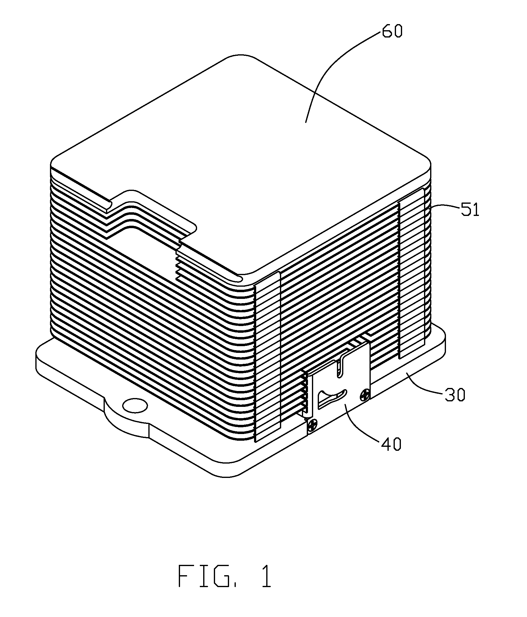
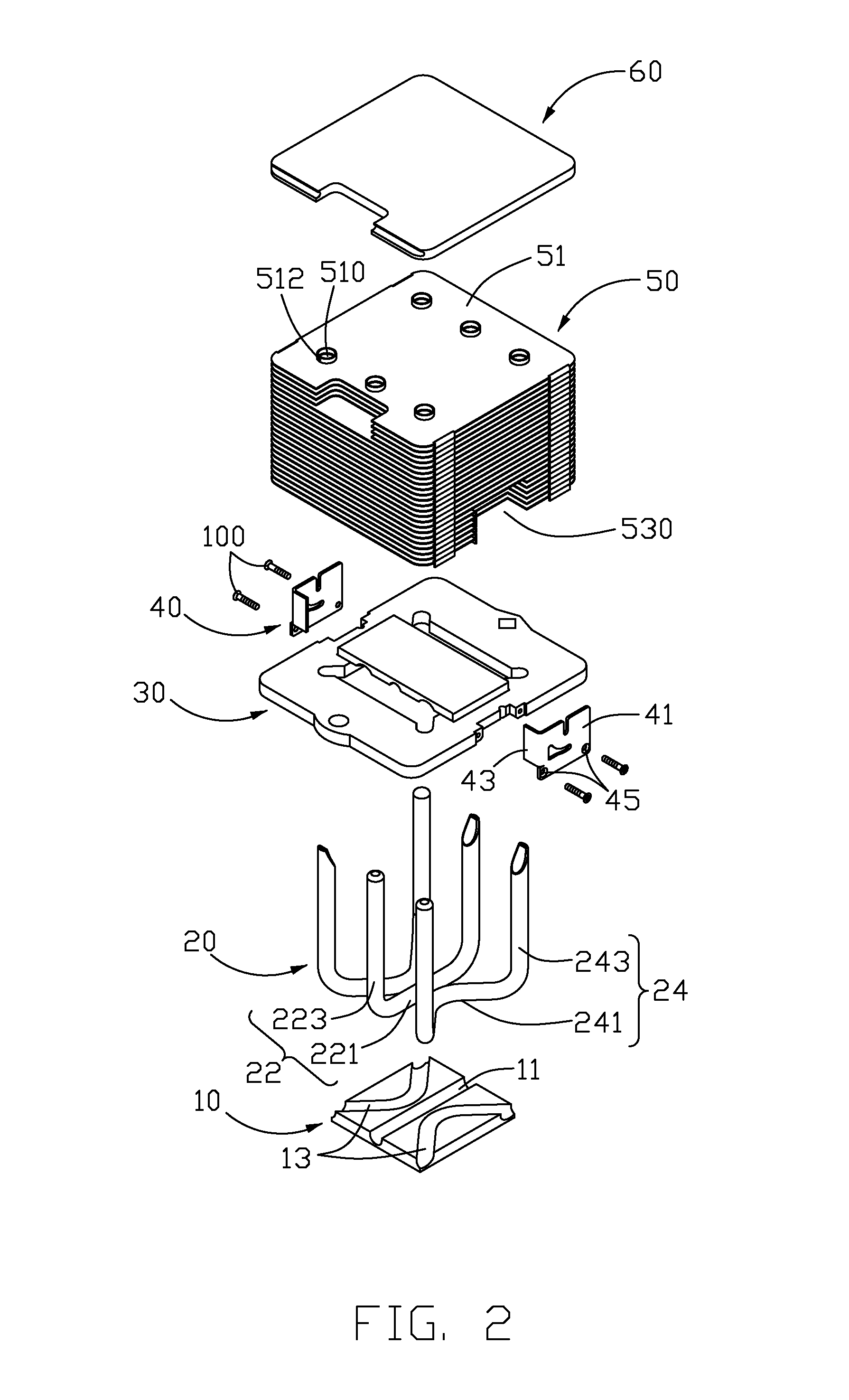
[0013]Referring to FIGS. 1 and 2, a heat dissipation device in accordance with a preferred embodiment of the present invention is utilized to dissipate heat originated by a heat-generating component (not shown). The heat dissipation device comprises a base consisting of a substrate 30 and a base plate 10, three heat pipes 20, two clamping pads 40 secured on two lateral sides of the substrate 30 of the base, a fin set 50 and a top plate 60 located on a top of the fin set 50. The substrate 30 cooperates with the base plate 10 to sandwich portions of the heat pipes 20 therebetween.

[0014]The base plate 10 is made of a metallic material with an outstanding heat conductivity, such as copper, and is rectangular in shape. The base plate 10 has a bottom surface for contacting with the heat-generating component, and defines a first groove 11 and two second grooves 13 in a top surface thereof. The first groove 11 is linear in shape and located at a middle of the base plate 10; the second groov...


PUM


Abstract

A heat dissipation device includes a base including a base plate made of a first heat conductive material and a substrate made of a second heat conductive material having a heat conductivity lower than that of the first heat conductive material. The substrate comprises a frame with a window receiving the base plate therein and an engaging plate spanning over the window. A fin set includes a plurality of fins parallel with and spaced from each other, and is mounted on the base. A heat pipe has an evaporating section sandwiched between the base plate and the engaging plate, and two condensing sections extending through the fin set and thermally connecting therewith. The evaporating section has a substantially V-shaped configuration.

Description

BACKGROUND OF THE INVENTION[0001]1. Field of the Invention[0002]The present invention relates generally to heat dissipation devices, and more particularly to a heat dissipation device for cooling a heat-generating electronic device.[0003]2. Description of Related Art[0004]With advancement of computer technology, electronic devices operate at a high speed. It is well known that the more rapidly the electronic devices operate, the more heat they generate. If the heat is not dissipated duly, the stability of the operation of the electronic devices will be impacted severely. Generally, in order to ensure the electronic device to run normally, a heat dissipation device is used to dissipate the heat generated by the electronic device.[0005]Typically, the heat dissipation device comprises a base formed from aluminum and contacting with the electronic device, a plurality of fins parallel to the base and three U-shaped heat pipes thermally connecting the base and the fins together. The heat ...

Claims


Application Information

Patent Timeline
IPC IPC(8): F28D15/00H05K7/20
CPCF28D15/0275H01L23/427H01L23/467H01L2924/0002H01L2924/00
Inventor ZHOU, ZHI-YONGXIAO, MIN-QIGAO, ZENG-JUN
Owner HON HAI PRECISION IND CO LTD
Why Eureka
Try Eureka