Ultrasound transducer for application in extreme climatic conditions

Active Publication Date: 2005-02-03
ADOLF THIES GMBH & CO KG
View PDF3 Cites 2 Cited by
  • Summary
  • Abstract
  • Description
  • Claims
  • Application Information

AI Technical Summary

Benefits of technology

[0026] The heat flow should go an as short way through the matching layer having a low heat conductivity as possible to keep the cooling effect by strong wind as small as possible. The

Problems solved by technology

From U.S. Pat. No. 4,890,488 it is known to fight icing in an ultrasound anemometer by m

Method used


Image

  • Ultrasound transducer for application in extreme climatic conditions
  • Ultrasound transducer for application in extreme climatic conditions

Examples


Example

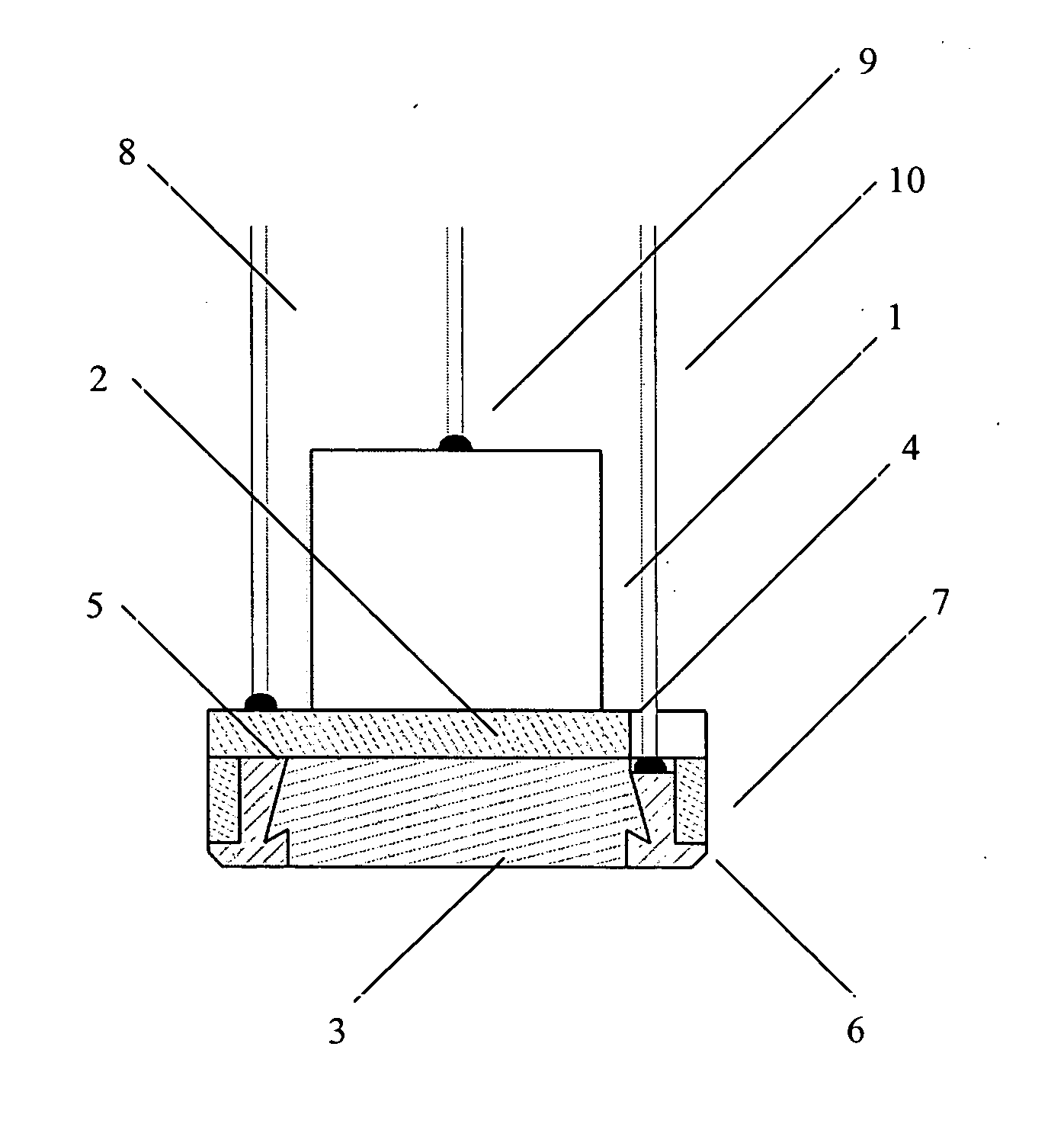
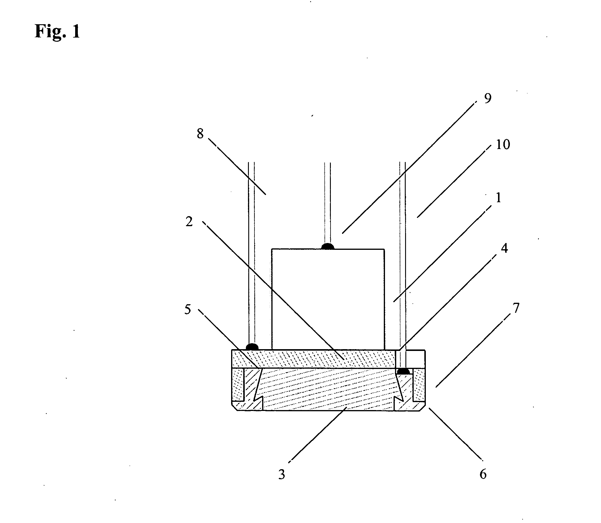
[0038] Referring now in greater detail to the drawing, the ultrasound transducer shown in FIG. 1 comprises an electromechanical transducer 1 having a piezo-electric or magneto-dynamic transducer material and an acoustically active surface. Further, the transducer 1 has a back connector electrode connected to a signal line 9, and a front connector electrode at its acoustically active surface. The transducer is operated by a voltage signal applied to its back electrode via the signal line 9. The front electrode of the transducer 1 is connected to a back connector electrode of a heating element 2 via a soft solder layer. Both, the front electrode of the transducer 1 and the back electrode of the heating element 3 are connected to a ground line 8. The heating element is operated by an electric current flowing from a front connector electrode connected to a heating line 10 to the back electrode connected to the ground line 8. The heating element 2 comprises a PTC-resistance material show...


PUM


Abstract

The invention relates to an ultrasound transducer in particular for application in ultrasound anemometry, comprising an electromechanical transducer (1) with an acoustically active surface, an acoustic matching layer (3) arranged between the acoustic surfaces of the converter and the exposed acoustic surfaces, and an electrical heating element (2). The heating element (2) is arranged between the acoustically active surfaces of the transducer (1) and the matching layer (3).

Description

CROSS REFERENCE TO RELATED APPLICATIONS [0001] This application is a continuation in part of International Patent Application PCT / EP 02 / 13360 filed Nov. 27, 2002 and claiming priority to co-pending German Patent Application No. 101 58 144.0-35 filed Nov. 27, 2001 both of which are entitled “Ultraschallwandler für den Einsatz unter extremen klimatischen Bedingungen”.FIELD OF THE INVENTION [0002] The invention relates to an ultrasound transducer for use in the field of metrology, particularly in the field of ultrasound anemometry. Even more particularly, the invention relates to an ultrasound transducer comprising an electromechanical transducer having an acoustically active surface, an acoustic matching layer which is arranged in front of the acoustically active surface of the transducer and which provide an exposed acoustic surface, and an electrical heating element. [0003] The ultrasound transducers which are mainly used in the field of metrology belong to the low to medium power r...

Claims


Application Information

Patent Timeline
IPC IPC(8): G01S7/521G10K11/00
CPCG10K11/004G01S7/521
Inventor BYZIO, WALDEMARWINDOLPH, HERBERT
Owner ADOLF THIES GMBH & CO KG
Why Eureka
Try Eureka