
Apparatus and associated method for making a floating gate cell with increased overlay between the control gate and floating gate

Active Publication Date: 2008-05-29
MACRONIX INT CO LTD
View PDF5 Cites 0 Cited by
  • Summary
  • Abstract
  • Description
  • Claims
  • Application Information

AI Technical Summary

Benefits of technology

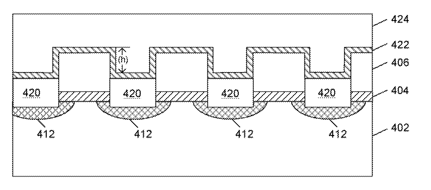
[0012]A method for fabricating a floating gate memory device comprises using a buried diffusion oxide that is below the floating gate thereby producing an increased step height between the floating gate and the buried diffusion oxide. The increased step height can produce a higher GCR, while still allowing decreased cell size using a virtual ground array design.

Problems solved by technology

Smaller cell sizes, however, often require smaller buried diffusion sizes, which are not necessarily compatible with conventional processing techniques.
For example, one problem that can occur as a result of the reduced buried diffusion sizes with conventional fabrication techniques is a reduced gate coupling ratio (GCR) between the control gate and floating gate.

Method used


Image

  • Apparatus and associated method for making a floating gate cell with increased overlay between the control gate and floating gate
  • Apparatus and associated method for making a floating gate cell with increased overlay between the control gate and floating gate
  • Apparatus and associated method for making a floating gate cell with increased overlay between the control gate and floating gate

Examples


Embodiment Construction

.”

BRIEF DESCRIPTION OF THE DRAWINGS

[0014]Features, aspects, and embodiments of the inventions are described in conjunction with the attached drawings, in which:

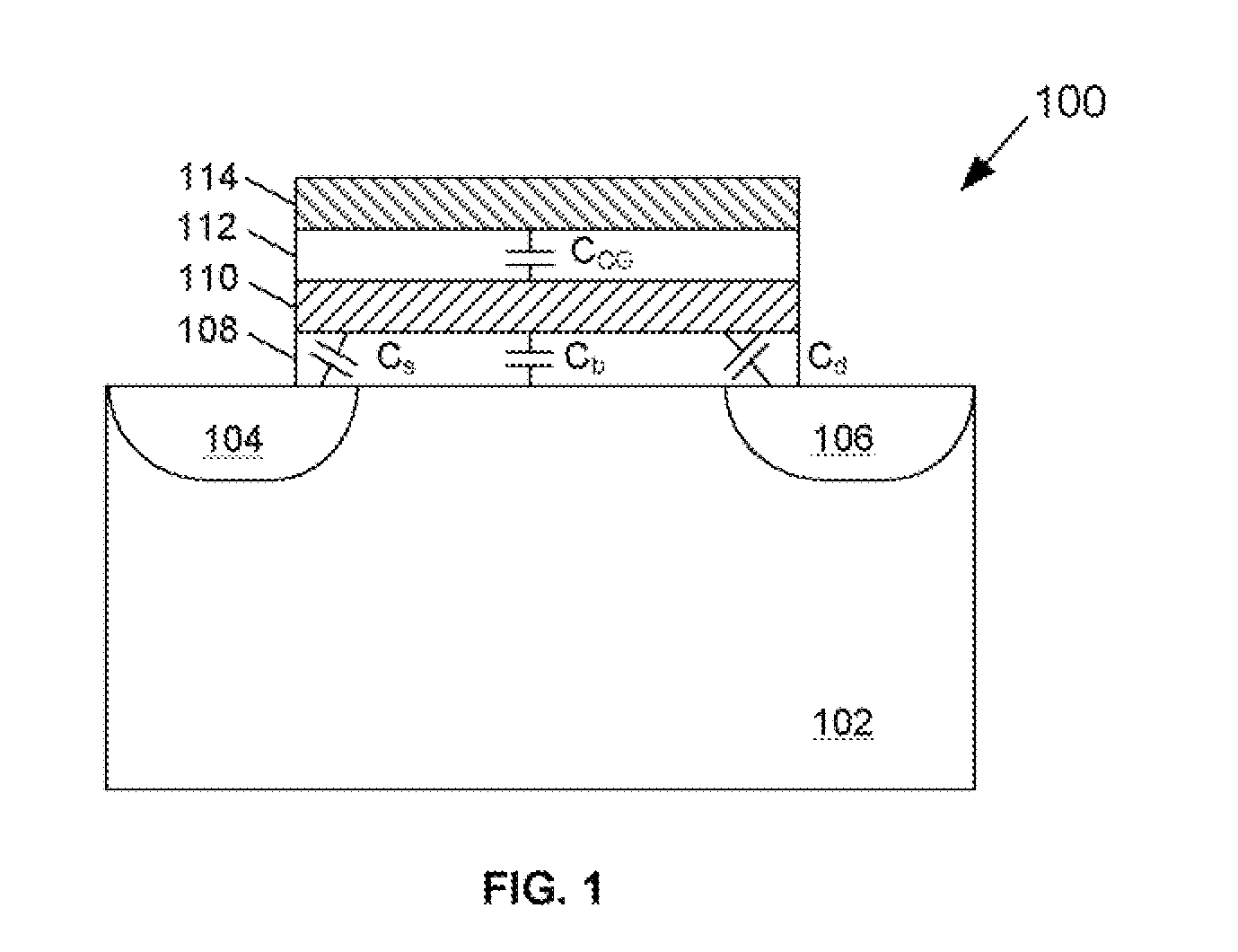
[0015]FIG. 1 is a schematic diagram illustrating a cross-sectional view of a conventional floating gate memory cell;

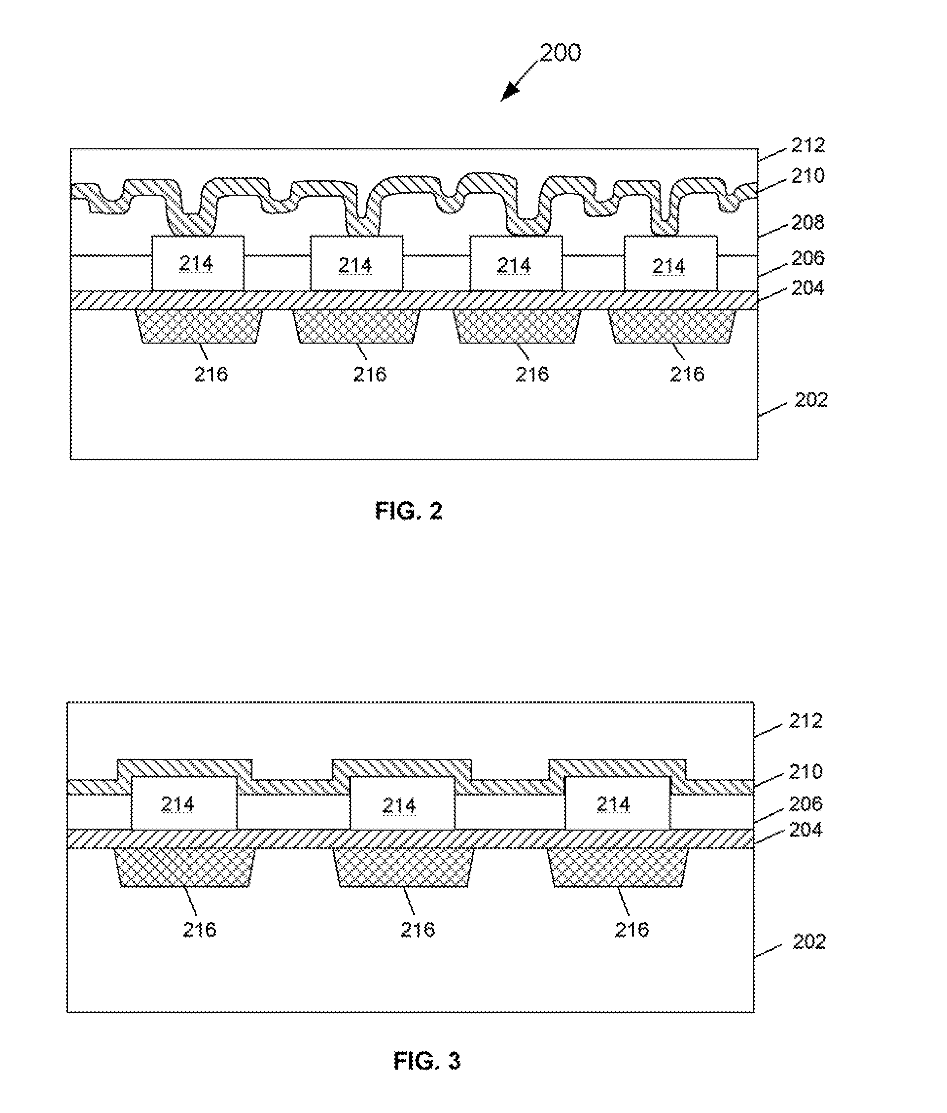
[0016]FIG. 2 is a schematic diagram illustrating a cross-sectional view of a floating gate memory device fabricated using a conventional fabrication process;

[0017]FIG. 3 is a schematic diagram illustrating a cross-sectional view of a floating gate memory device fabricated using a conventional fabrication process that does not include a fourth poly step;

[0018]FIG. 4 is a schematic diagram illustrating a cross-sectional view of a floating gate memory cell fabricated in accordance with one embodiment; and

[0019]FIGS. 5A-5G are schematic diagrams illustrating an exemplary process for fabricating the floating gate memory device of FIG. 4 in accordance with one embodiment.

DETAILED DESCRIPTION

[0020]In the methods descri...


PUM


Abstract

A method for fabricating a floating gate memory device comprises using a buried diffusion oxide that is below the floating gate thereby producing an increased step height between the floating gate and the buried diffusion oxide. The increased step height can produce a higher GCR, while still allowing decreased cell size using a virtual ground array design.

Description

BACKGROUND[0001]1. Field of the Invention[0002]The embodiments described herein are directed to methods for fabricating non-volatile memory devices, and more particularly to methods for fabricating floating-gate memory devices using virtual ground arrays.[0003]2. Background of the Invention[0004]FIG. 1 is a schematic representation of a conventional floating gate memory cell 100. Memory cell 100 comprises a substrate 102 with diffusion regions 104 and 106 formed therein. The diffusion regions correspond to the source and drain of FET-type device. According to one example, substrate 102 can be a P-type substrate and diffusion regions 104 and 106 can be N-type diffusion regions. In other embodiments, cell 100 can comprise an N-type substrate 102 with P-type diffusion regions 104 and 106. Although it will be understood that a P-type substrate is generally preferred.[0005]Cell 100 further comprises a gate dielectric layer, sometimes referred to as a tunnel dielectric layer 108 formed ov...

Claims


Application Information

Patent Timeline
IPC IPC(8): H01L29/788H01L21/336
CPCH01L21/28273H01L29/42324H01L27/11521H01L29/40114H10B41/30
Inventor LIU, CHEN-CHINHUANG, LAN TINGYANG, LING KUEYWU, PO HSUAN
Owner MACRONIX INT CO LTD
Learn More