
Methods and apparatus for controlling series-connected leds

a series-connected led and led package technology, applied in the direction of electric variable regulation, process and machine control, instruments, etc., can solve the problems of impede integration, inefficiency and waste of conversion energy, led packages including one or more leds integrated together with some type of power conversion circuitry,

Active Publication Date: 2008-05-29
SIGNIFY NORTH AMERICA CORP
View PDF99 Cites 129 Cited by
  • Summary
  • Abstract
  • Description
  • Claims
  • Application Information

AI Technical Summary

Benefits of technology

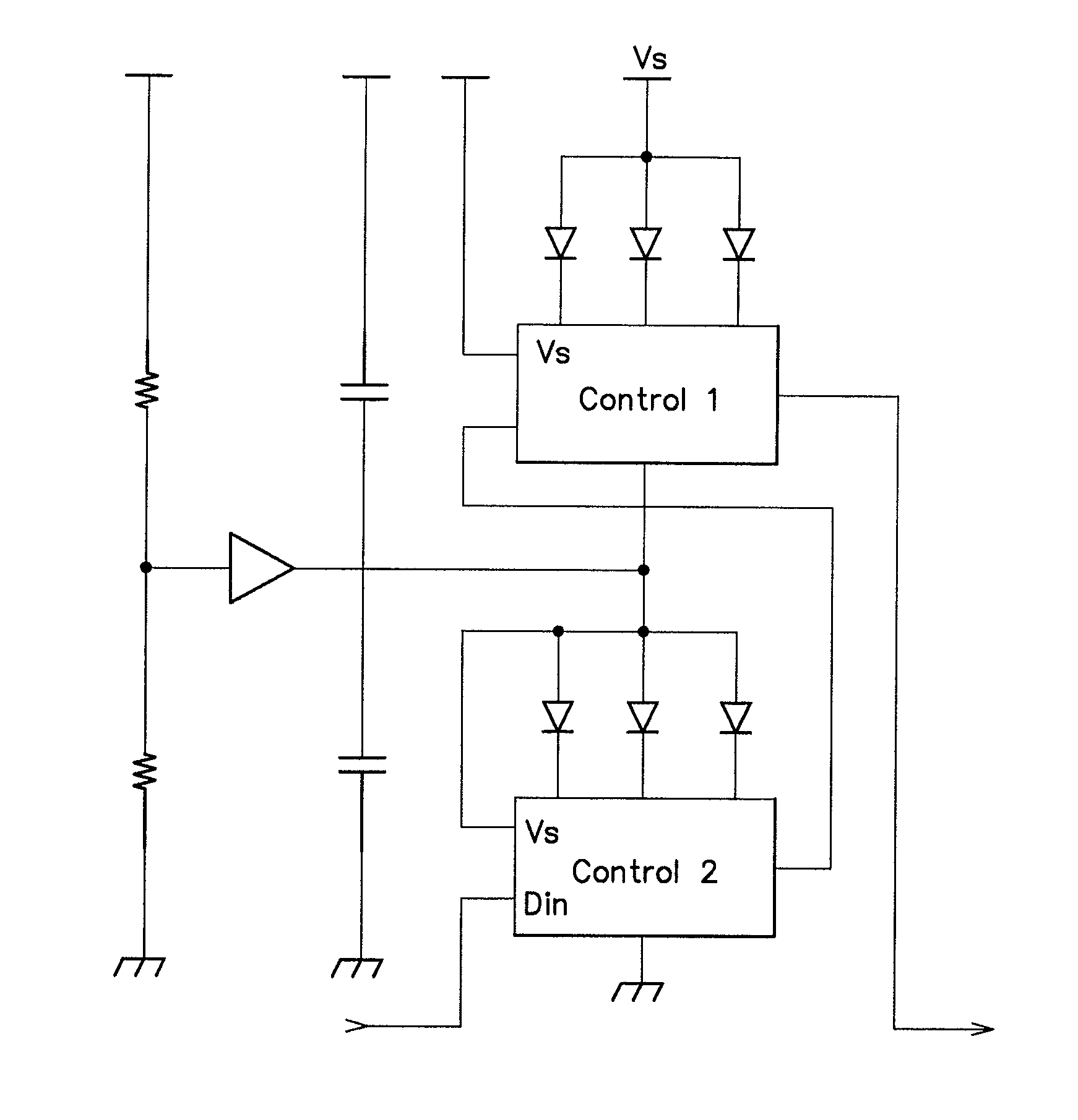
The patent text discusses a method and apparatus for controlling LED-based light sources that can operate at higher voltages than individual LEDs. By connecting multiple LEDs in series, the overall operating voltage of the system can be increased, allowing for operation at higher voltages than the individual LEDs. This is useful in situations where the expected operating voltage of the LEDs is below the minimum required to energize them. The apparatus includes multiple series-connected LEDs, controllable current paths connected in parallel with the LEDs, and a controller to control the current paths. The controller can adjust the current paths to increase the amount of current that is diverted around the LEDs, reducing the required operating voltage. The apparatus can be implemented as integrated circuits or packaged for easy installation. The technical effect is to enable LED-based light sources to operate at higher voltages than individual LEDs, and to control the current paths to increase the brightness of the LEDs while using a single power source.

Problems solved by technology

One impediment to widespread adoption of low-voltage LEDs and low-voltage LED-based lighting units as light sources in applications in which generally higher power supply voltages are readily available is the need to convert energy from one voltage to another, which, in many instances, results in conversion inefficiency and wasted energy.
Furthermore, energy conversion typically involves power management components of a type and size that generally impede integration.
Presently, LED packages including one or more LEDs integrated together with some type of power conversion circuitry are not available.
One significant barrier to the integration of LEDs and power conversion circuitry relates to the type and size of power management components needed to convert energy to the relatively lower voltage levels typically required to drive LEDs.
For example, voltage conversion apparatus (e.g., DC-to-DC converters) typically utilize inductors as energy storage elements, which cannot be effectively integrated in silicon chips to form integrated circuits.
Inductor size is also a serious barrier to integrated circuit implementations, both in terms of an individual inductor component as part of any integrated circuit, as well as more specifically in LED packages.
Furthermore, inductors typically cannot be made to be both efficient and handle a relatively wide range of voltages, and inductive converters generally require significant capacitance to store energy during converter operation.
Thus, conventional voltage conversion apparatus based on inductors have a fairly significant footprint when compared with a single or multiple LED packages, and do not readily lend themselves to integration with LED packages.
Capacitive voltage conversion systems present similar challenges.
If efficiency is a salient requirement, these systems must have practical ratios with a unity numerator or denominator; hence, either the input or output are low voltage at higher current, which effectively decreases efficiency.
Thus, efficiency inevitably needs to be compromised at any particular operating voltage to decrease complexity and make simpler fractions.

Method used


Image

  • Methods and apparatus for controlling series-connected leds
  • Methods and apparatus for controlling series-connected leds
  • Methods and apparatus for controlling series-connected leds

Examples


Embodiment Construction

[0058]Various embodiments of the present invention are described below, including certain embodiments relating particularly to LED-based light sources. It should be appreciated, however, that the present disclosure is not limited to any particular manner of implementation, and that the various embodiments discussed explicitly herein are primarily for purposes of illustration. For example, the various concepts discussed herein may be suitably implemented in a variety of environments involving LED-based light sources, other types of light sources not including LEDs, environments that involve both LEDs and other types of light sources in combination, and environments that involve non-lighting-related devices alone or in combination with various types of light sources.

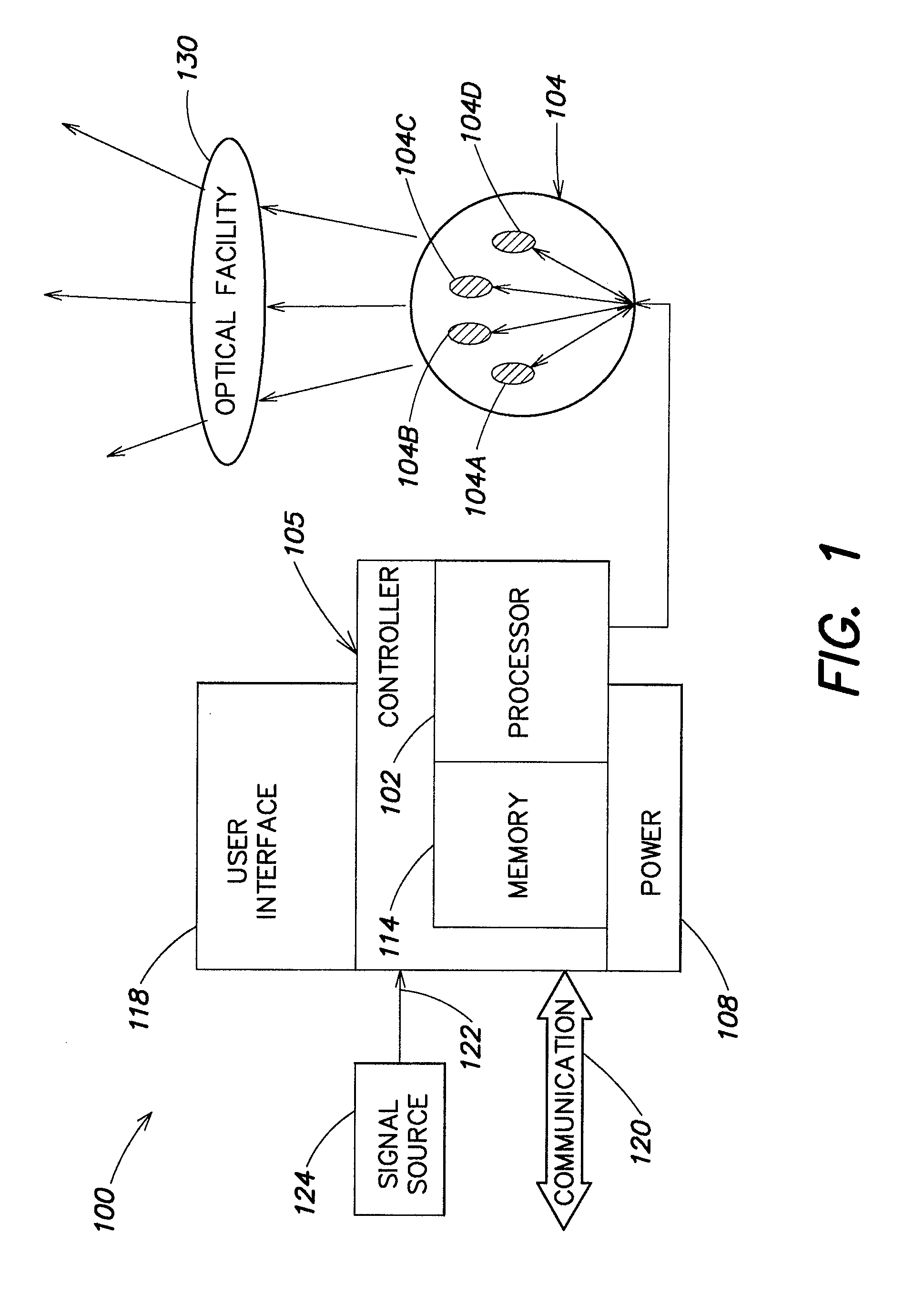
[0059]FIG. 1 illustrates one example of a lighting unit 100 according to one embodiment of the present disclosure. Some general examples of LED-based lighting units similar to those that are described below in connection w...


PUM


Abstract

Methods and apparatus for controlling series-connected LEDs. Two or more LEDs are connected in series between a first node and a second node, wherein a series current flows between the nodes when an operating voltage is applied across the nodes. One or more controllable current paths are connected in parallel with at least a first LED for at least partially diverting the series current around at least the first LED. A controller monitors at least one parameter representative of the operating voltage, determines a maximum number of the series-connected LEDs that can be energized by the operating voltage, and controls the controllable current path(s) so as to increase an amount of the series current that is diverted around at least the first LED when the maximum number is less than a total number of all of the LEDs connected in series. In one example, the foregoing may be implemented as an integrated circuit package to provide a lighting apparatus suitable for automotive applications.

Description

CROSS-REFERENCES TO RELATED APPLICATIONS[0001]The present application claims the benefit, under 35 U.S.C. § 119(e), of the following U.S. provisional applications, each of which is incorporated herein by reference:[0002]Ser. No. 60 / 865,353, filed Nov. 10, 2006, entitled “Methods and Apparatus for Controlling Devices in a Networked Lighting System;”[0003]Ser. No. 60 / 883,626, filed Jan. 5, 2007, entitled “Methods and Apparatus for Providing Resistive Lighting Units;” and[0004]Ser. No. 60 / 956,309, filed Aug. 16, 2007, entitled “Methods and Apparatus for Controlling Series-connected LEDs.”BACKGROUND[0005]Light emitting diodes (LEDs) are semiconductor-based light sources often employed in low-power instrumentation and appliance applications for indication purposes. LEDs conventionally are available in a variety of colors (e.g., red, green, yellow, blue, white), based on the types of materials used in their fabrication. This color variety of LEDs recently has been exploited to create nove...

Claims


Application Information

Patent Timeline
Patent Type & Authority Applications(United States)
IPC IPC(8): H05B37/02H05B44/00
CPCH05B33/0857H05B33/083H05B45/48H05B45/20Y02B20/30
Inventor LYS, IHOR A.
Owner SIGNIFY NORTH AMERICA CORP
Learn More