Image capturing apparatus and control method therefor
- Summary
- Abstract
- Description
- Claims
- Application Information
AI Technical Summary
Benefits of technology
Problems solved by technology
Method used
Image

Examples
first embodiment
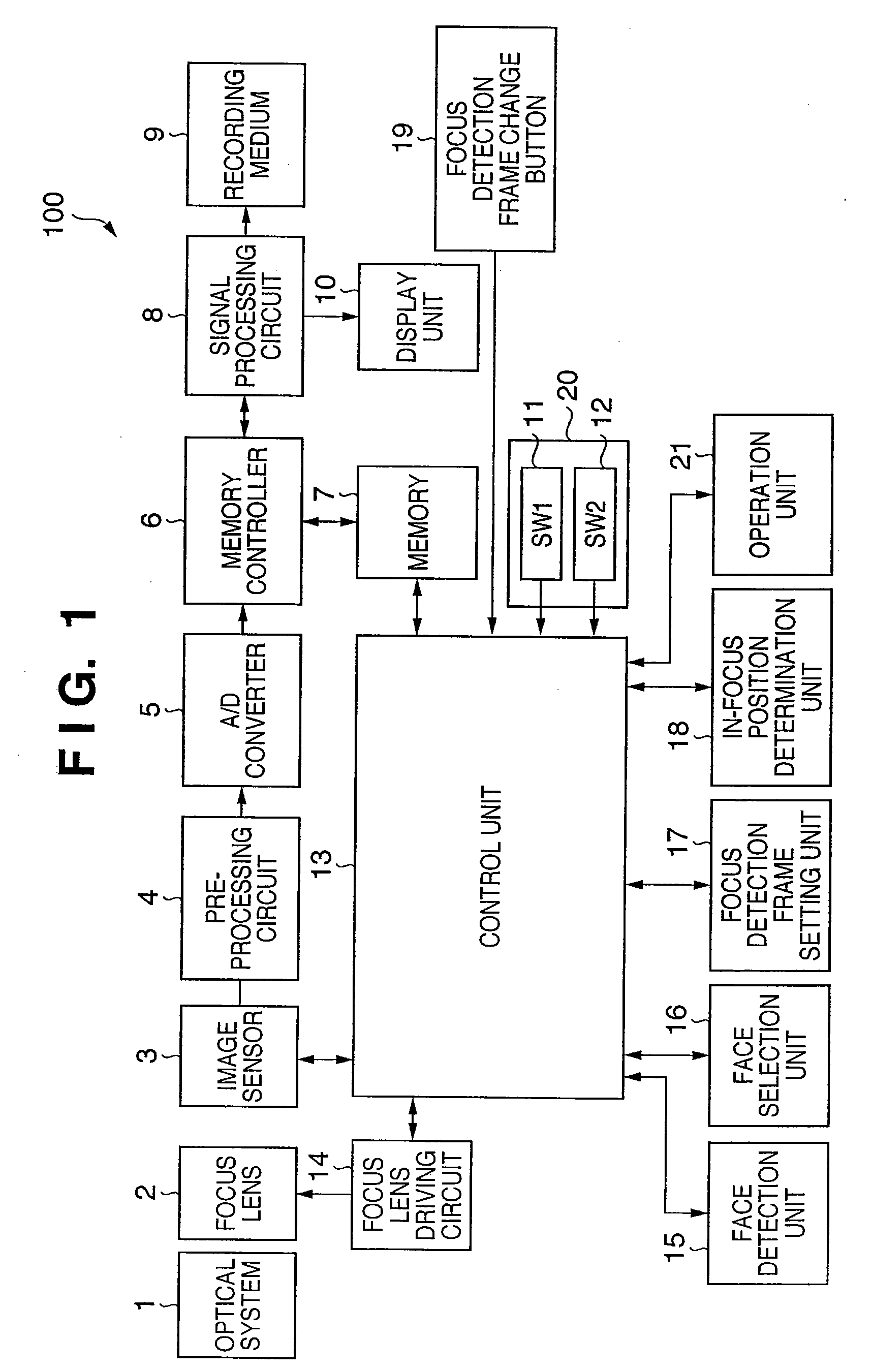
[0023]FIG. 1 is a block diagram showing the schematic arrangement of a digital camera 100 which sets a focus detection frame and focus detection area using a face detection function to execute auto-focusing in the first embodiment.
[0024]The digital camera 100 according to the first embodiment comprises an optical system 1 and focus lens 2, and causes an image sensor 3 to photo-electrically convert the light imaged by them. The output signal from the image sensor 3 is digitized via a preprocessing circuit 4 and A / D converter 5. The preprocessing circuit 4 comprises a CDS circuit and nonlinear amplification circuit for removing output noise. The digital signal is stored in a memory 7 via a memory controller 6, converted into an image (image information) by a signal processing circuit 8, and recorded on a recording medium 9. A display unit 10 displays the image converted by the signal processing circuit 8. A control unit 13 controls the display of the image on the display unit 10.
[0025...
second embodiment
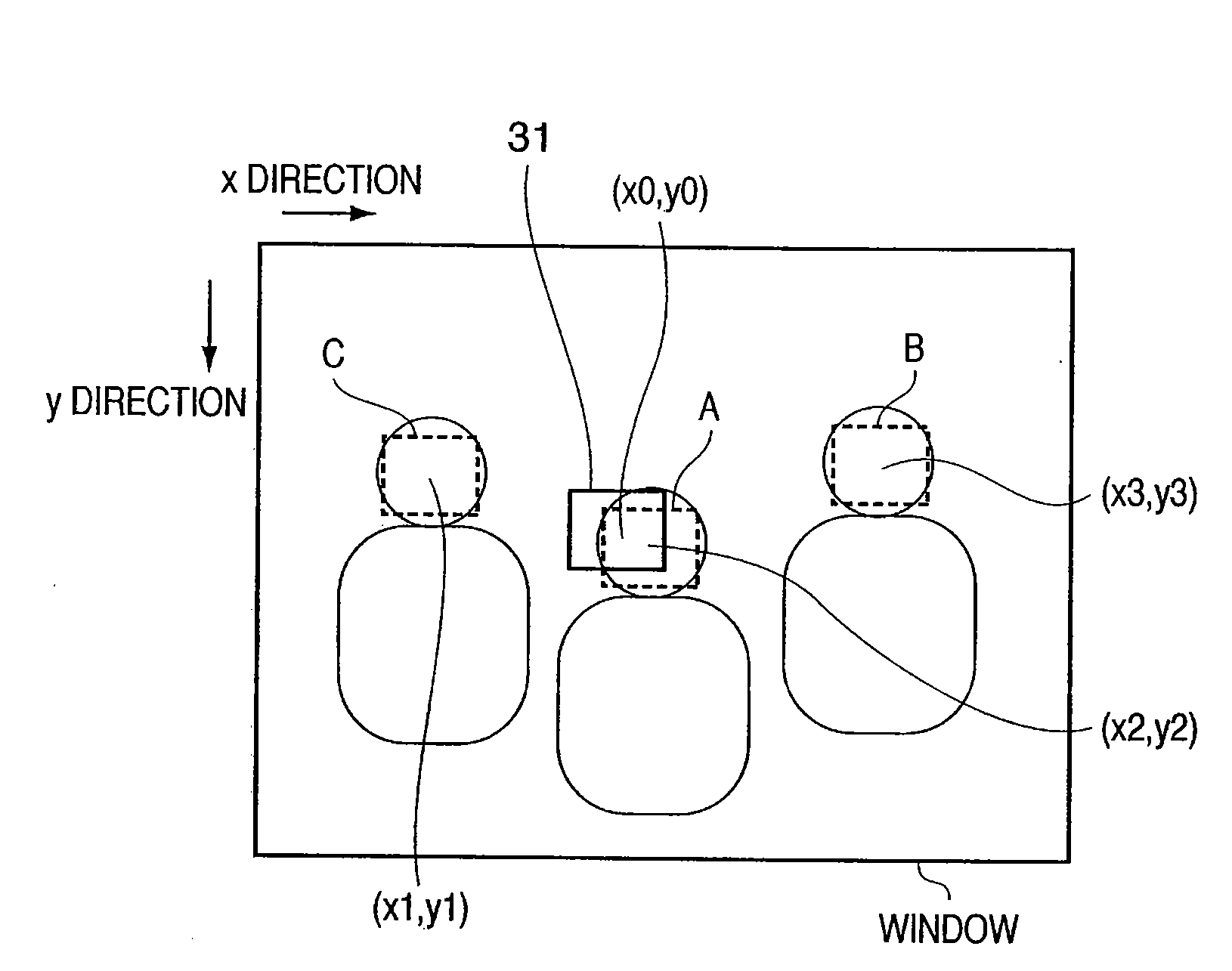
[0049]The second embodiment will be described. In the first embodiment, the selected face moves to the right in the window. In the second embodiment, the selected face moves from the center or its vicinity to the periphery.
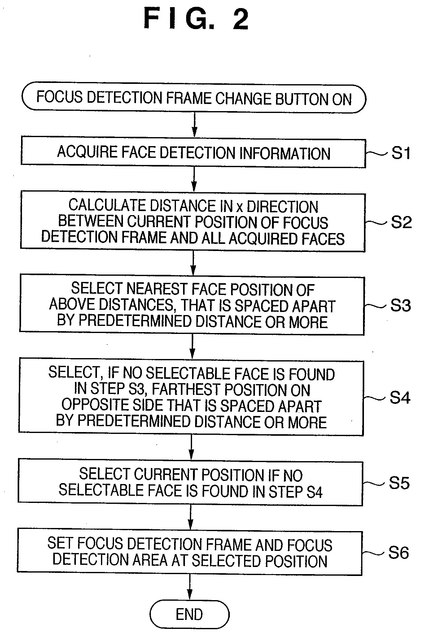
[0050]The second embodiment is different from the first embodiment in the determination methods in steps S2, S3, and S4. This difference will be explained with reference to the flowchart shown in FIG. 4.
[0051]In step S12, a distance di from the center position is calculated by:
di=√{(xi−xc)2+(yi−yc)2}−√{(x0−xc)2+(y0−yc)2}
where (xc, yc) is the position of the center or its vicinity of the window.
[0052]In steps S13 and S15, a face position that exhibits a minimum distance di which satisfies:
di>TH
is selected.
[0053]If no face is selectable in step S13, a face position that exhibits a maximum absolute value of a distance di which satisfies:
di<−TH
is selected in steps S14 and S16.
[0054]As described above, according to the second embodiment, it is possible to sequentia...
third embodiment
[0056]The third embodiment will be described. In the third embodiment, a method of setting the priority order of the detected faces and determining their selection order using the resultant priority order will be explained. The basic arrangement of a digital camera is the same as that in the first embodiment.
[0057]The priority order setting of the detected faces is as follows.
[0058]For example, priority order setting is done using the face size and position in the following way. First, a weighting coefficient corresponding to the size of the detected face is calculated in accordance with the graph shown in FIG. 5A. A weighting coefficient corresponding to the distance from the center to the face is also calculated in accordance with the graph shown in FIG. 5B. As the size of the face increases and the face position becomes nearer to the center, the weighting coefficient is set at a larger value. The product of the two weighting coefficients is calculated to give a higher priority le...
PUM
 Abstract
Description
Claims
Application Information
 - Generate Ideas
- Intellectual Property
- Life Sciences
- Materials
- Tech Scout
- Unparalleled Data Quality
- Higher Quality Content
- 60% Fewer Hallucinations
Browse by: Latest US Patents, China's latest patents, Technical Efficacy Thesaurus, Application Domain, Technology Topic, Popular Technical Reports.
© 2025 PatSnap. All rights reserved.Legal|Privacy policy|Modern Slavery Act Transparency Statement|Sitemap|About US| Contact US: help@patsnap.com