Radio resource allocation method and telecommunication apparatus

a radio resource allocation and radio telecommunication technology, applied in electrical equipment, network traffic/resource management, wireless commuication services, etc., can solve problems such as the inability to fix a mobile terminal, the inability to reduce the downlink throughput, and the inability to fix the mobile terminal, so as to reduce the amount of control information, and reduce the effect of effective utilization of radio resources

Active Publication Date: 2008-05-29
FUJITSU LTD
View PDF14 Cites 38 Cited by
  • Summary
  • Abstract
  • Description
  • Claims
  • Application Information

AI Technical Summary

Benefits of technology

[0032](i) A flexible resource allocation in accordance with the number of patterns is enabled by pre-determining a pattern of radio resources to be allocated, and a notification of the allocated radio resource information requires only a minimum amount of information, thereby enabling a reduction in control information and an effective utilization of a radio resource.
[0033](ii) The notification of information related to a permissible delay together with a request for a radio resource makes it possible to allocate the radio resource by considering a delay, satisfying the permissible delay.
[0034](iii) The definition of an allocation pattern by using one or plural items of the elements comprising the three-dimensional resource, i.e., frequency, time, and code, as a radio resource makes it possible to carry out a flexible resource allocation and also to reduce the amount of control info

Problems solved by technology

Since the resources usable at a base station are limited, it cannot be fixed for a mobile terminal.
Such a case results in the control information and downlink data sharing a predetermined amount of resources and the volume of downlink data allowed to be transmitted together being reduced if the amount of control information is large, thus generating the problem of decreasing the downlink throughput.
The amount of notification information proportionately increases with the number of solids and therefore, if the form of the spatial range information becomes complex, a large number of resources

Method used


Image

  • Radio resource allocation method and telecommunication apparatus
  • Radio resource allocation method and telecommunication apparatus
  • Radio resource allocation method and telecommunication apparatus

Examples


Embodiment Construction

[0060]The following is a detailed description of the preferred embodiment of the present invention by referring to the accompanying drawings.

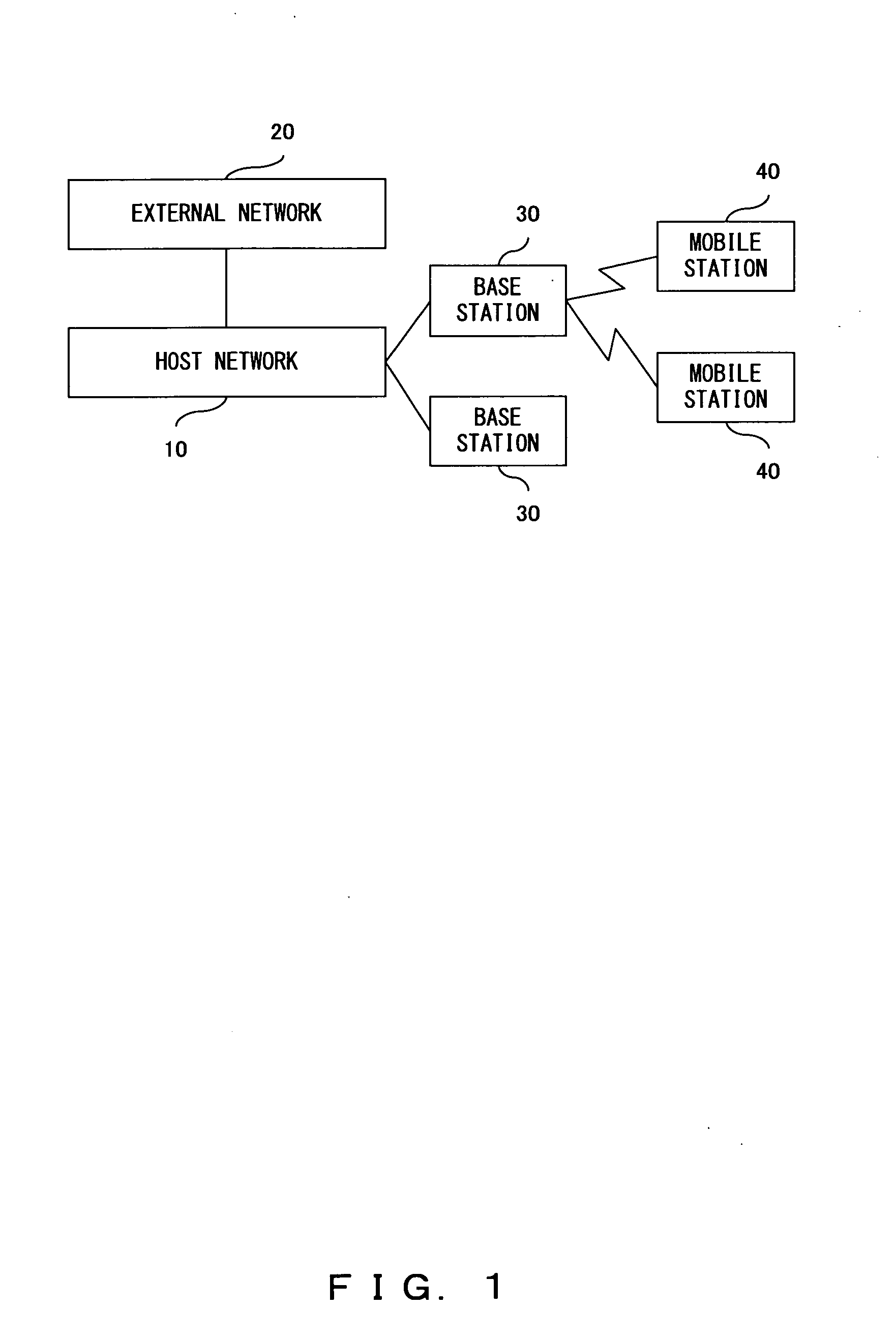
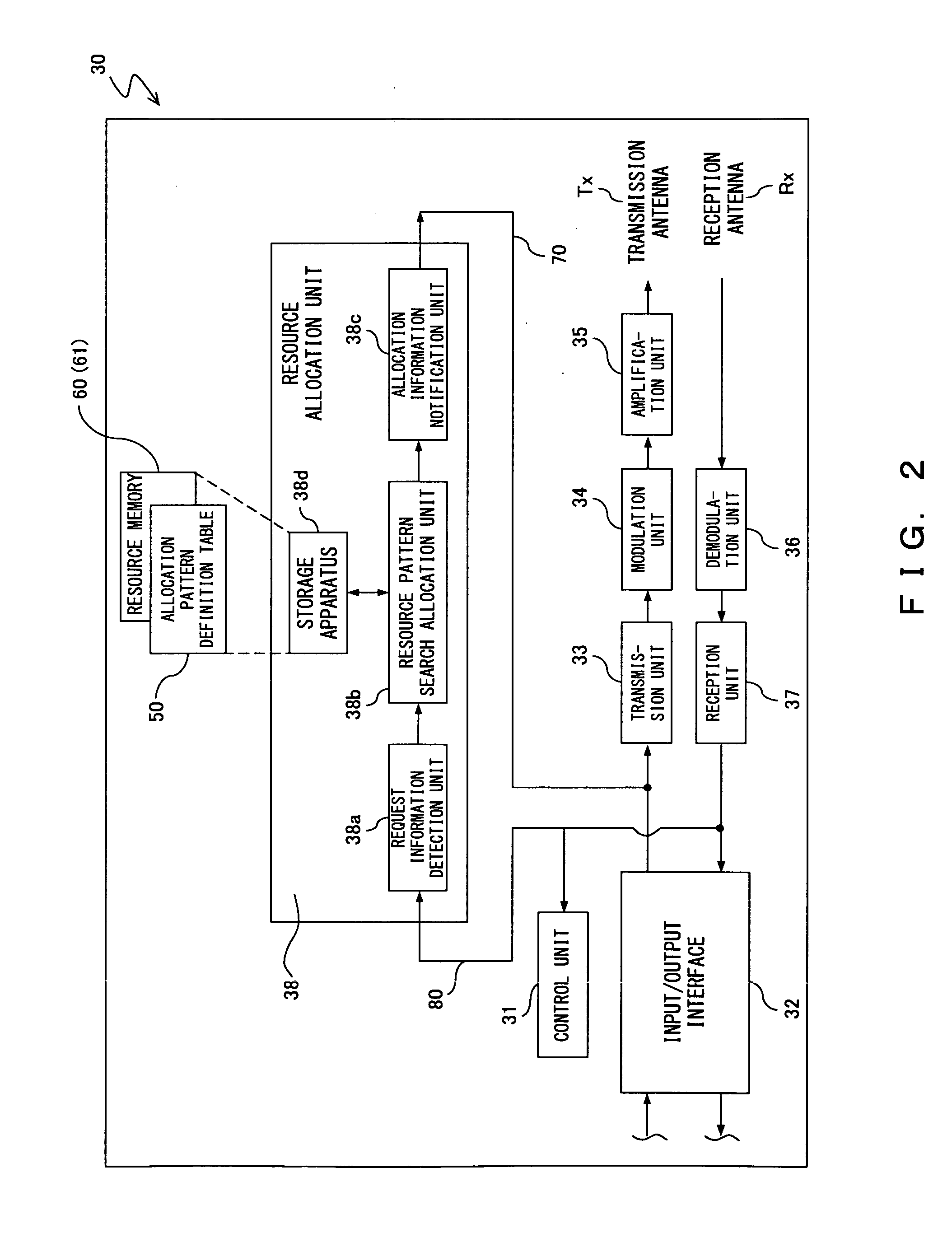
[0061]FIG. 1 is a conceptual diagram exemplifying a configuration of a radio telecommunication system comprising a radio telecommunication apparatus according to a preferred embodiment of the present invention; FIG. 2 is a block diagram exemplifying a configuration of a radio telecommunication apparatus constituting a base station according to the present embodiment; FIG. 3 is a block diagram exemplifying a configuration of a radio telecommunication apparatus constituting a mobile station according to the present embodiment; and FIG. 4 is a block diagram exemplifying, in greater detail, a configuration of a part of a radio telecommunication apparatus constituting a mobile station according to the present embodiment.

[0062]The radio telecom system according to the present embodiment comprises a plurality of base stations 30 and a plurality of mob...


PUM


Abstract

A radio resource allocation method for use in a radio telecommunication system for a first radio telecommunication apparatus and a second telecommunication apparatus carrying out a radio telecommunication by using an allocated radio resource, comprising selecting a resource allocation pattern identifying a combination of radio resources allocatable within a resource management space from among a pre-prepared plurality of resource allocation patterns, and notifying the second radio telecommunication apparatus of pattern identifier information identifying the selected resource allocation pattern and of startup position information thereof within the resource management space.

Description

CROSS-REFERENCE TO RELATED APPLICATIONS[0001]This application is a continuation of international PCT application No. PCT / JP2005 / 012643 filed on Jul. 8, 2005.BACKGROUND OF THE INVENTION[0002]1. Field of the Invention[0003]The present invention relates to a radio resource allocation technique and a radio telecommunication technique and in particular to a technique effectively applicable to a radio telecommunication system performing radio telecommunications by reserving and using a set of plurality kinds of radio resources.[0004]2. Description of the Related Art[0005]Internet connections using mobile terminals have become popular and higher speed telecommunications are in demand. A mobile terminal connects itself to a base station by utilizing a radio resource, and the base station connects itself to another base station or to an external network such as the Internet so that a path is eventually established to a telecommunication correspondent. In order to enable a plurality of mobile...

Claims


Application Information

Patent Timeline
IPC IPC(8): H04Q7/00H04B1/707H04J3/16H04J11/00H04W28/26H04W72/04H04W72/06H04W72/08
CPCH04W72/044H04W72/06H04W72/563H04W72/04
Inventor FUJITA, HIROSHITAJIMA, YOSHIHARU
Owner FUJITSU LTD
Why Eureka
Try Eureka