Electrostatic pressure transducer and manufacturing method therefor

a technology of electrostatic pressure transducer and manufacturing method, which is applied in the direction of electrical transducer, deaf-aid set, and condenser microphone sensitivity degradation, etc., can solve the problems of difficult to increase the acoustic resistance of the passage, difficult to reduce the width (or the cross-sectional size) of the passage, and achieve the effect of improving the stability of the electrostatic pressure transducer, reducing the displacement of the diaphragm, and small volum

Inactive Publication Date: 2008-05-29
YAMAHA CORP
View PDF1 Cites 61 Cited by
  • Summary
  • Abstract
  • Description
  • Claims
  • Application Information

AI Technical Summary

Benefits of technology

[0025]In a second aspect of the present invention, an electrostatic pressure transducer includes a stopper plate (or a substrate), a plate that is formed using a plate electrode film deposited on the stopper plate, a diaphragm that is formed using a diaphragm electrode film, and a plurality of cantilevers, each of which is deflected at a distal end thereof toward the diaphragm, which is thus depressed. Due to the internal stresses of the cantilevers, it is possible to increase a first gap between the plate and the diaphragm, thus improving the stability of the electrostatic pressure transducer.
[0026]In the above, the stopper plate forms a back cavity; the plate electrode film has a first through-hole; a second gap having an acoustic resistance, which is exerted between the back cavity and the first through-hole, is formed between the peripheral end of the diaphragm and the opening edge of the stopper plate; at least one second through-hole communicating with the first through-hole and the second gap is formed in the external portion of the diaphragm externally of the back cavity; and the first gap communicates with the first through-hole. Herein, an air pressure causing the displacement of the diaphragm is transmitted to the diaphragm via the first through-hole. When a non-acoustic space, which is defined by the diaphragm oppositely to the plate, has a relatively small volume and is closed in an airtight manner, the pressure applied to the non-acoustic space causes a reaction so as to reduce the displacement of the diaphragm, thus degrading the sensitivity. In addition, there is a possibility in that the diaphragm may be unexpectedly destroyed due to the air pressure difference between the air pressure of the non-acoustic space and the atmospheric pressure. Such a possibility can be eliminated because the second gap having the acoustic resistance, which is exerted between the diaphragm and the stopper plate, can be reduced to be smaller than the thickness of a sacrifice film that is deposited between the diaphragm electrode film and the stopper plate. Thus, it is possible to improve the...

Problems solved by technology

However, when sound waves enter into the non-acoustic space via the passage connecting between the acoustic space and the non-acoustic space, which are partitioned by use of the diaphragm, the condenser microphone is degraded in sensitivity.
It is difficult to increase the acoustic resistance of the passage so as to cope with sound waves of low-frequency ranges, in other words, it is d...

Method used


Image

  • Electrostatic pressure transducer and manufacturing method therefor
  • Electrostatic pressure transducer and manufacturing method therefor
  • Electrostatic pressure transducer and manufacturing method therefor

Examples


first embodiment

1. First Embodiment

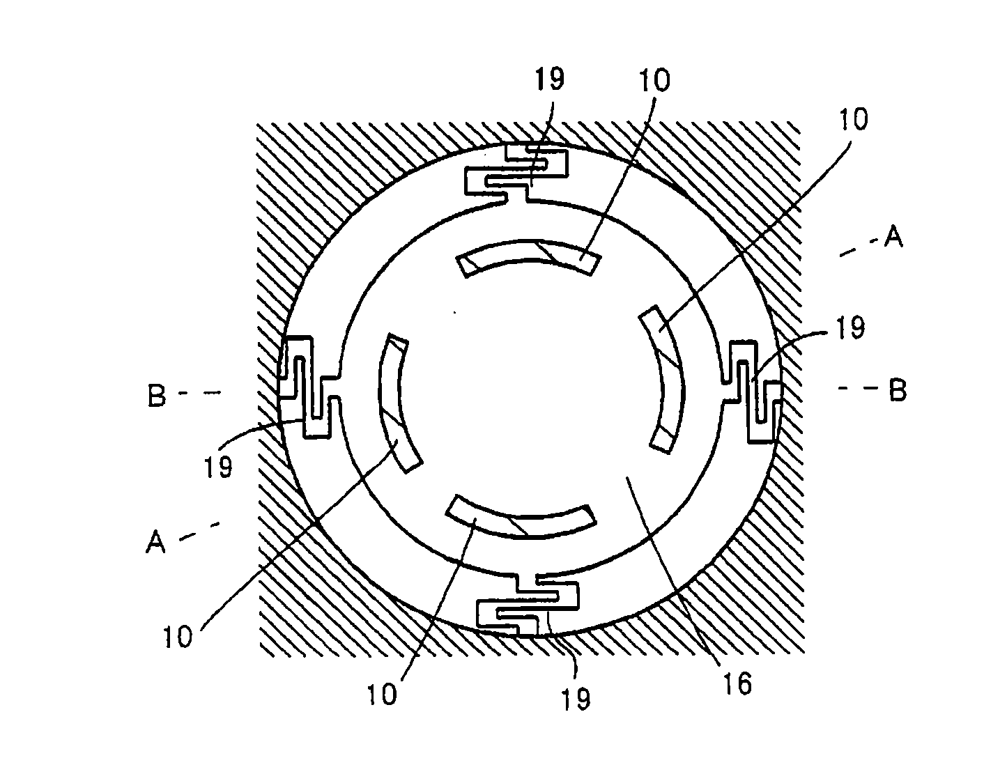
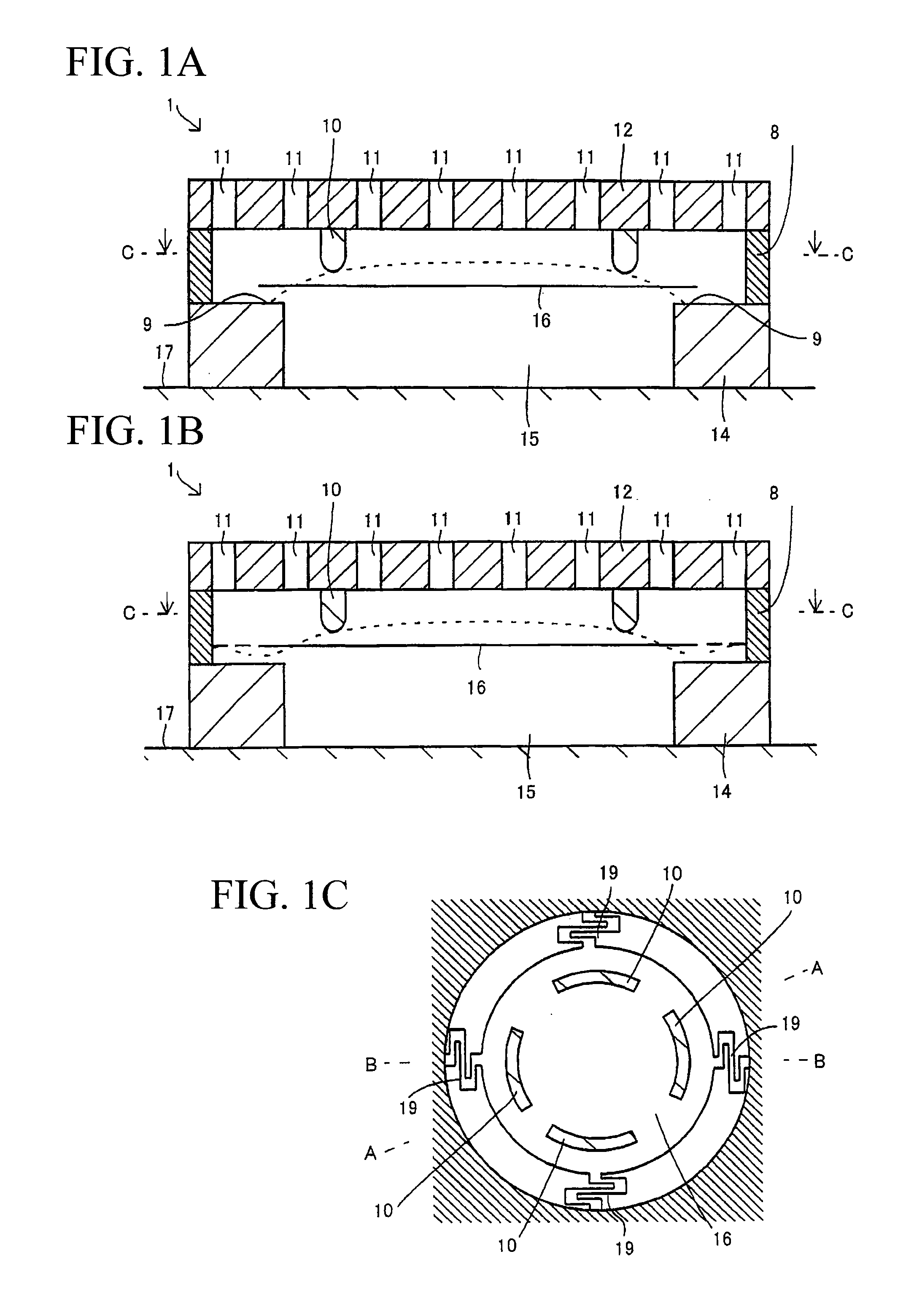
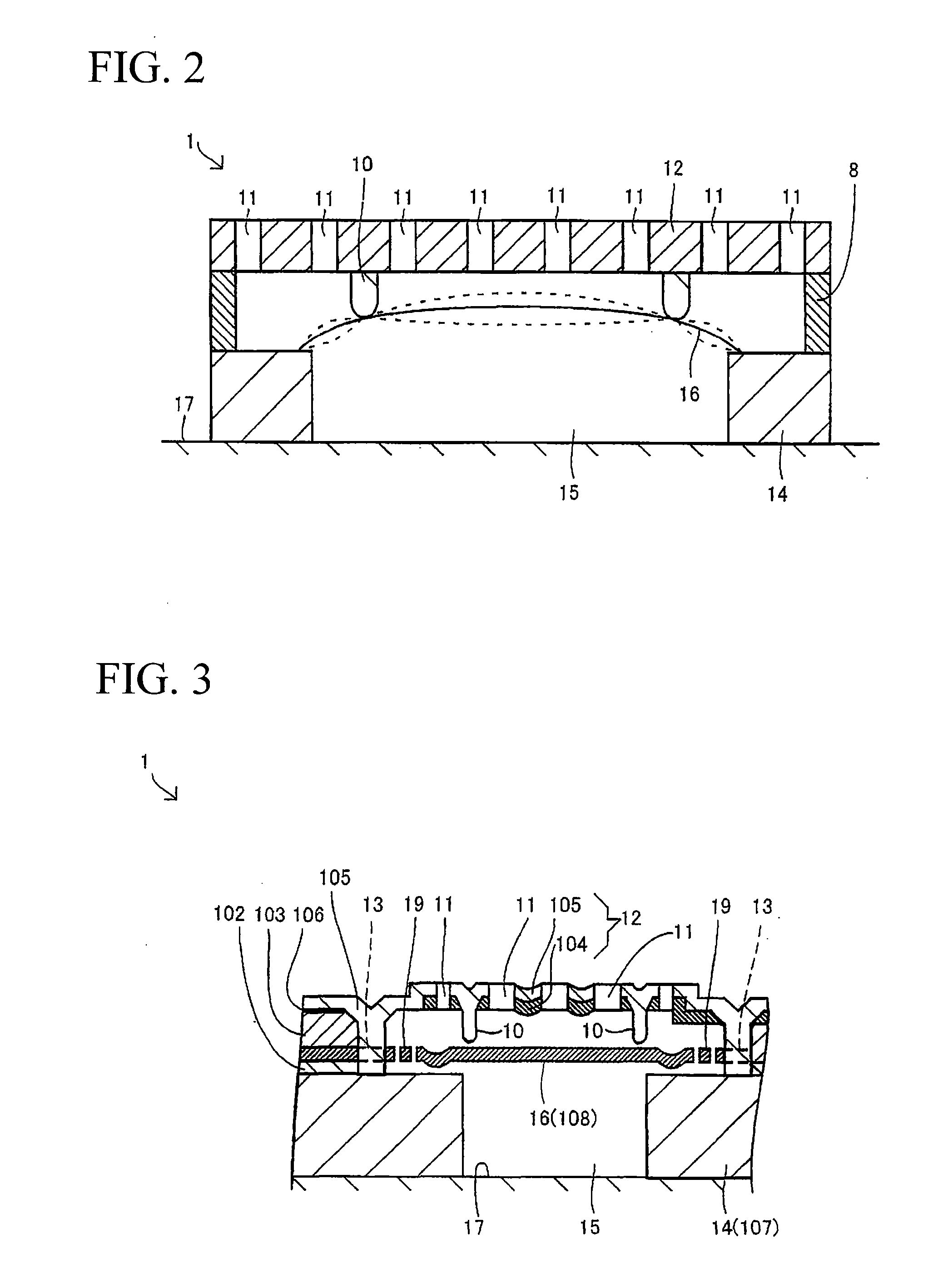
[0079]FIGS. 1A, 1B, and 1C are sectional views diagrammatically showing the constitution of a condenser microphone 1, without specific illustrations regarding laminated structures of films, in accordance with a first embodiment of the present invention. The cutting planes of FIGS. 1A and 1B are perpendicular to the surface of a plate 12. The cutting plane of FIG. 1C is parallel with the surface of the plate 12. FIG. 1C shows a diaphragm 16 viewed from the plate 12. Specifically, FIG. 1A is a longitudinal sectional view taken along line A-A in FIG. 1C, and FIG. 1B is a longitudinal sectional view taken along line B-B in FIG. 1C.

[0080]The condenser microphone 1 includes the plate 12 forming a fixed electrode and the diaphragm 16 forming a vibrating electrode. The plate 12 is fixed to a ring-shaped wall 8. The diaphragm 16 is bridged across the internal space defined by the wall 8 via springs 19.

[0081]A substrate 14 serving as a stopper plate is fixed to a wiring por...

second embodiment

2. Second Embodiment

[0144]Next, a condenser microphone 1001 will be described in detail in accordance with a second embodiment of the present invention. FIGS. 13A and 13B are sectional views diagrammatically showing the essential parts of the condenser microphone 1001. The condenser microphone 1001 is a chip in which plural thin films are deposited on a substrate (or a stopper plate) 1016 composed of silicon and which is encapsulated in a package constituted of a wiring substrate and a cover (both not shown).

[0145]A through-hole H4 is formed to run through the substrate 1016. An opening 1161 of the through hole H4 forms an opening of a back cavity BC that is closed by the wiring substrate (not shown).

[0146]A first spacer film 1015 is deposited on the surface of the substrate 1016 and is formed using an insulating film composed of SiO2, for example. A circular through-hole H3 is formed to run through the first spacer film 1015.

[0147]A diaphragm electrode film 1014 is deposited on the...


PUM


Abstract

An electrostatic pressure transducer (e.g., a condenser microphone) includes a plate having a plurality of holes and forming a fixed electrode, a diaphragm forming a vibrating electrode, at lease one spacer that is positioned between the plate and the diaphragm in the ring-shaped internal area internally of the peripheral end of the diaphragm, and a stopper plate having an opening, which is positioned opposite to the plate with respect to the diaphragm. The diaphragm vibrates relative to the plate in such a way that, due to electrostatic attraction, the internal portion thereof moves close to the plate while the external portion thereof moves opposite to the plate, wherein the peripheral end thereof partially comes in contact with the opening edge of the stopper plate. Thus, it is possible to realize flat frequency characteristics while improving the sensitivity in low-frequency ranges.

Description

BACKGROUND OF THE INVENTION[0001]1. Field of the Invention[0002]The present invention relates to electrostatic pressure transducers such as condenser microphones adapted to MEMS (Micro-Electro-Mechanical Systems). The present invention also relates to manufacturing methods of electrostatic pressure transducers.[0003]This application claims priority on Japanese Patent Application No. 2006-281889 and Japanese Patent Application No. 2007-81423, the contents of which are incorporated herein by reference.[0004]2. Description of the Related Art[0005]It is conventionally known that electrostatic pressure transducers, in particular, condenser microphones, have been manufactured by way of MEMS (Micro-Electro-Mechanical System) manufacturing processes. Japanese Patent Application Publication No. 2004-506394 teaches a miniature broadband transducer serving as a condenser microphone. This condenser microphone includes a plate forming a fixed electrode and a diaphragm forming a vibrating electro...

Claims


Application Information

Patent Timeline
IPC IPC(8): H04R25/00
CPCH04R19/016H04R19/005H01L29/84H01L29/00
Inventor SATO, AKIYOSHISUZUKI, YUKITOSHI
Owner YAMAHA CORP
Why Eureka
Try Eureka