Transmission headstock for test stands

a technology for transmissions and test stands, which is applied in the direction of structural/machine measurement, instruments, manufacturing tools, etc., can solve the problems of inability to duplicate the rotational and tilting position of the transmission as it would be installed in a vehicle, and the lubrication conditions of the transmission, for example, may not be accurately simulated by the transmission test, so as to increase the time during which the test cell can be utilized

Inactive Publication Date: 2008-05-29
AVL TEST SYST
View PDF6 Cites 20 Cited by
  • Summary
  • Abstract
  • Description
  • Claims
  • Application Information

AI Technical Summary

Benefits of technology

[0007]The transmission can be installed onto the test unit, and the test unit can be moved into and out of a test cell. The example test unit is capable of replicating the orientation of the transmission when installed in a vehicle to provide more representative test data. Furthermore, the adjustments to the test unit can be done outside of a test cell to increase the time during which the test cell can be utilized.

Problems solved by technology

To avoid resonances the fixtures are inherently stiff and heavy.
Usually the test stand is not adjustable so that the rotational and tilting position of the transmission as it would be installed in a vehicle cannot be duplicated.
As a result, the lubrication conditions of the transmission, for example, may not be accurately simulated by the transmission test.
Dynamometer test cells are very expensive so that it is important to maximize test cell time available to test transmissions.

Method used


Image

  • Transmission headstock for test stands
  • Transmission headstock for test stands
  • Transmission headstock for test stands

Examples


Embodiment Construction

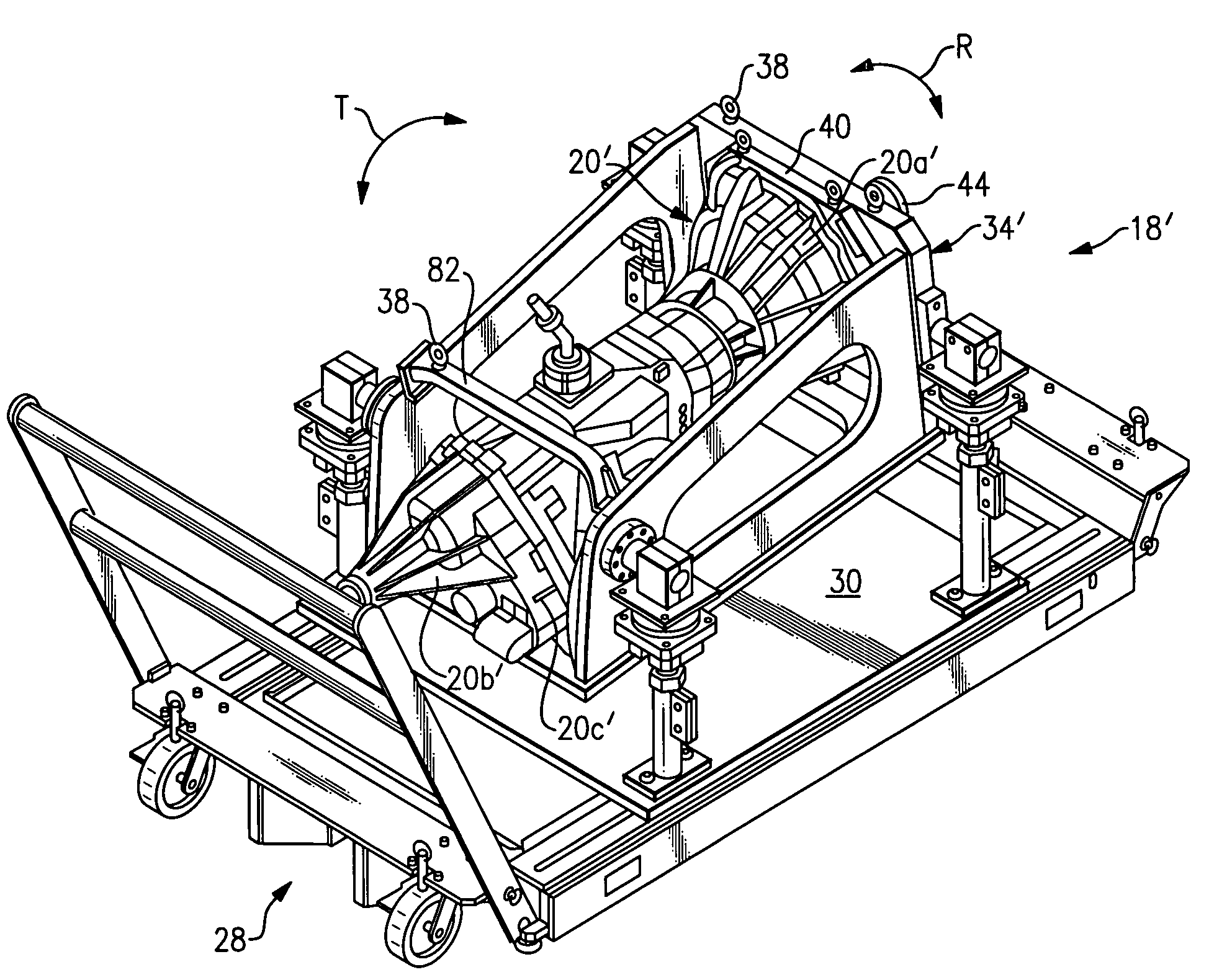
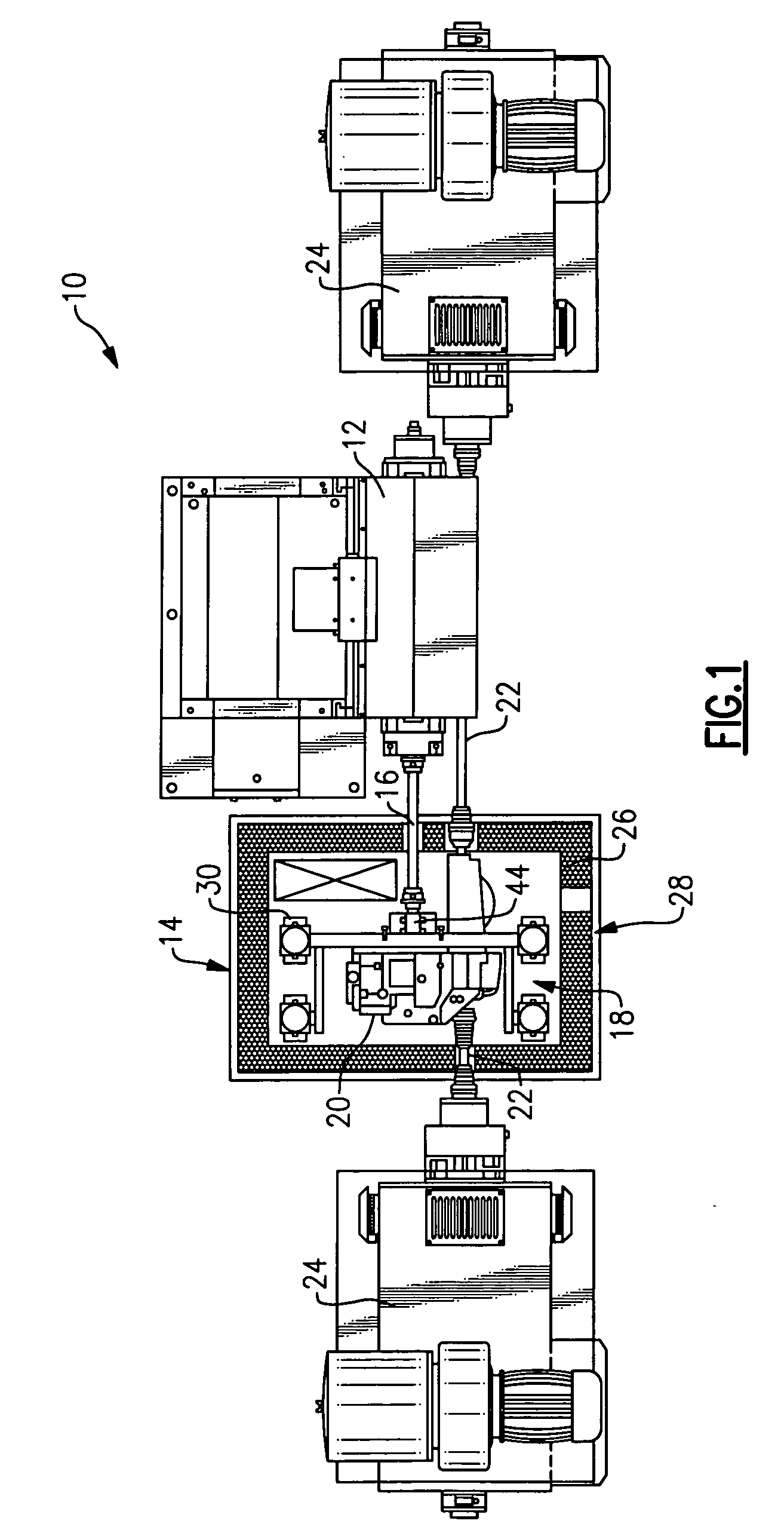
[0015]A test cell 10 is shown in FIG. 1. The test cell 10 includes an electric motor 12 for rotationally driving a transmission 20. The transmission 20 is part of a portable test unit 14 that can be moved into and out of test cells in a substantially ready-to-test state. The test unit 14 includes a portable cart 28 with a base plate 30 supporting a stand 18. The base plate 30 is supported on wheels in the example embodiment. The transmission 20 is mounted on the stand 18 and is connected to the electric motor 12 by a drive shaft 16.

[0016]The particular transmission 20 shown in FIG. 1 is for a front wheel drive arrangement. Output shafts 22 couple the transmission 20 to dynamometers 24, which exert a load on the transmission 20 for the type of test shown in FIG. 1. A loaded, cold test is shown in FIG. 1, which uses a cold box 26 mounted on the stand 18 to surround the transmission 20. The cold box 26 and dynamometers may be omitted for other tests.

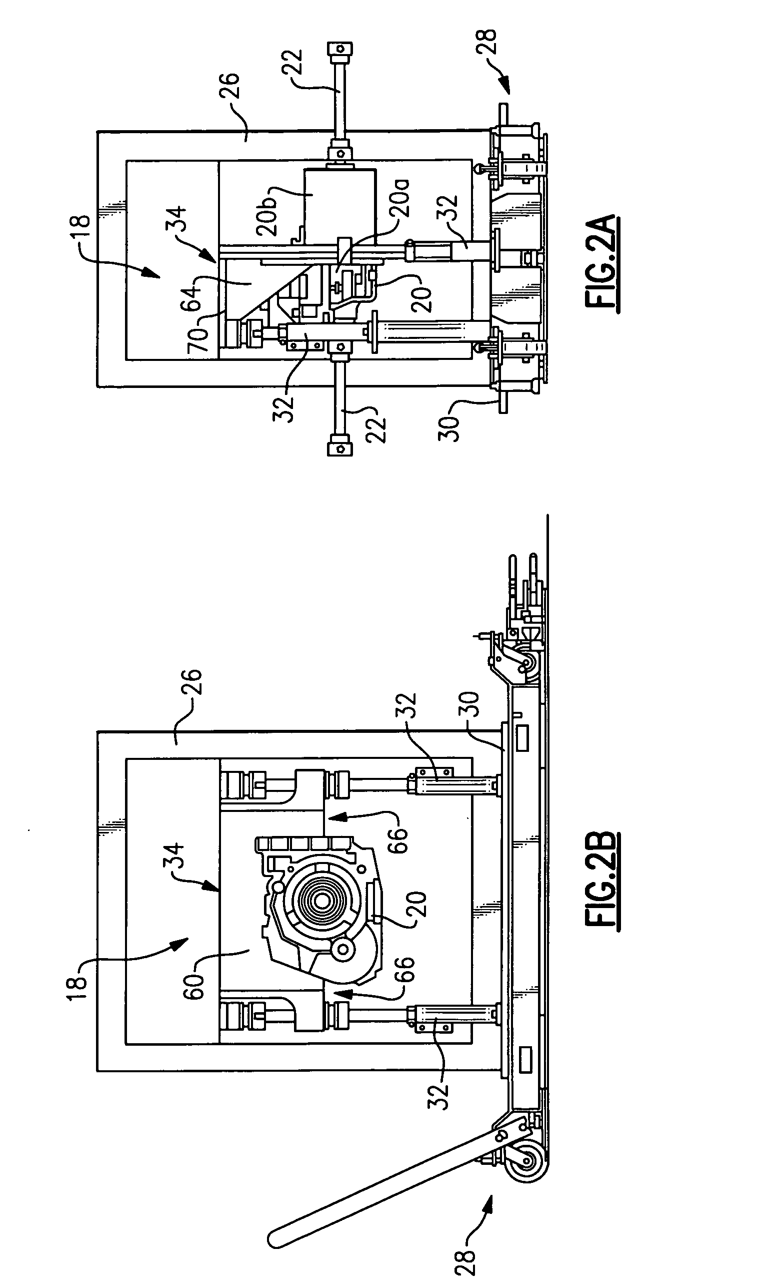
[0017]Referring to FIGS. 2A-3, the s...


PUM

PropertyMeasurementUnit
lengthaaaaaaaaaa
rotational angleaaaaaaaaaa
tilt angleaaaaaaaaaa

Abstract

A mobile test unit for testing a powertrain component such as a transmission is used in a test cell. A test unit includes a movable, generally horizontal base plate, and a frame spaced from the base plate. A headstock is secured to the frame for supporting the transmission. An adjustable support, which is arranged on each of four corners of the frame in the example embodiment, interconnects the frame to the base plate. The adjustable supports are movable in a vertical direction, in one example, between multiple positions to achieve a desired orientation relative to the base plate. In particular, the orientation of the frame is adjusted to obtain a desired rotational and / or tilt angle that corresponds to a rotational and / or tilt angle of the transmission when installed into a vehicle. The transmission can be installed onto the test unit, and the test unit can be moved into and out of a test cell. The example test unit is capable of replicating the orientation of the transmission when installed in a vehicle to provide more representative test data. Furthermore, the adjustments to the test unit can be done outside of a test cell to increase the time during which the test cell can be utilized.

Description

BACKGROUND OF THE INVENTION[0001]This invention relates to a fixture for supporting a vehicle transmission during a test procedure.[0002]Transmissions are developed in test cells where the design and durability of the transmission can be evaluated. A typical test cell includes an electric motor for driving the transmission. A test cell may also include dynamometers that are coupled to one or more output shafts of the transmission. The test cell includes a test stand fixed to a bed plate that is permanently attached to the floor of the test cell. In preparation for a test, the transmission is brought into the test cell and fastened to the test stand. A unique headstock is used to support each type of transmission. Test stands are designed to avoid resonant frequencies (vibrations) in the operational speed range. To avoid resonances the fixtures are inherently stiff and heavy. Usually the test stand is not adjustable so that the rotational and tilting position of the transmission as i...

Claims


Application Information

Patent Timeline
Patent Type & Authority Applications(United States)
IPC IPC(8): G01L3/00B23Q3/00
CPCG01M13/026G01M13/02
Inventor BARNES, KENPOSCH, PETERKOPECKY, WOLFGANGORTH, WALTER
Owner AVL TEST SYST
Why Eureka
Try Eureka