
System and Program Product for Incremental Design Reduction via Iterative Overapproximation and Re-Encoding Strategies

a technology of incremental reduction and computer program product, applied in the field of testing and verification, can solve the problems of inability to tolerate, the result polluted by design errors, and the inability of consumers to accept, so as to reduce logic

Inactive Publication Date: 2008-05-29
GLOBALFOUNDRIES INC
View PDF14 Cites 8 Cited by
  • Summary
  • Abstract
  • Description
  • Claims
  • Application Information

AI Technical Summary

Benefits of technology

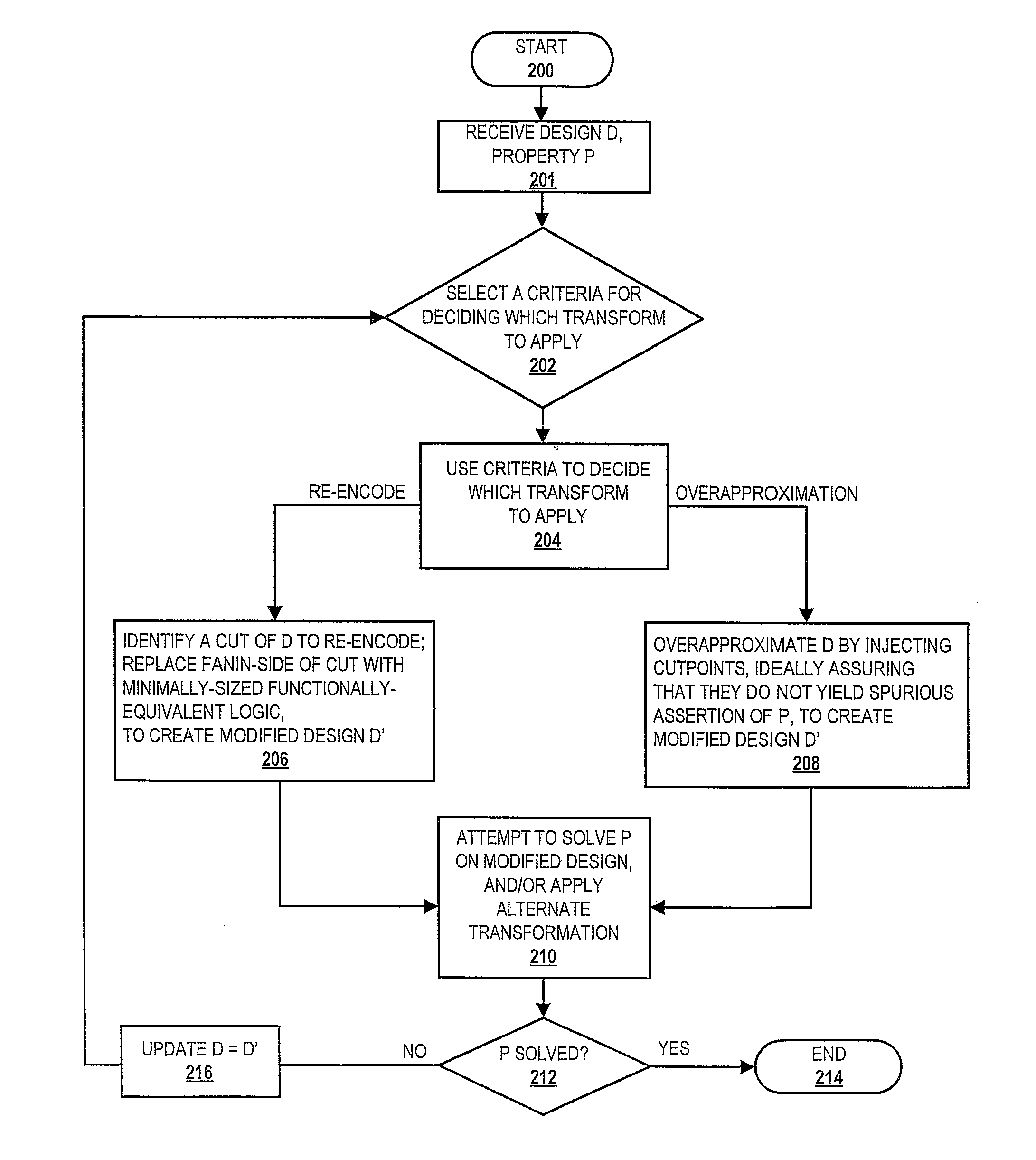
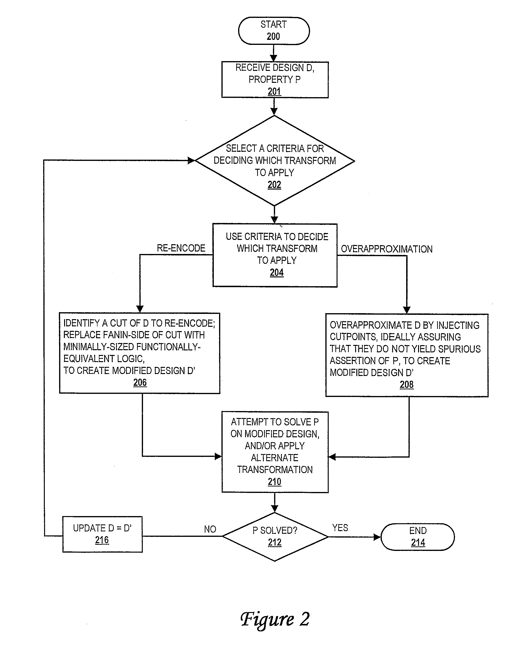
[0015]In the present invention, the particular synergy between employed overapproximation method and the employed re-encoding method results in several benefits. The structural overapproximation technique employed by the present invention turns sequentially-driven logic into combinationally-driven logic, and more generally injects random gates deeper into the cone of the design. This helps the re-encoding technique of the present invention, because the latter is primarily adept at reducing logic near random gates and is the weakest at eliminating purely sequential logic.

Problems solved by technology

Whether the impact of errors in design would be measured in human lives or in mere dollars and cents, consumers of circuit products have lost tolerance for results polluted by design errors.
Consumers will not tolerate, by way of example, miscalculations on the floor of the stock exchange, in the medical devices that support human life, or in the computers that control their automobiles.
Because the functional hardware verification time for a design grows in relation to the number of logic elements, functional hardware verification of complex systems is one of the most time-consuming computing tasks today.
As mentioned above, functional hardware verification is a computationally expensive process; for sequential designs, functional hardware verification is a PSPACE-complete problem (by algorithmic complexity analysis) and hence generally requires resources which are exponential with respect to the size of the design under verification.
Many prior art functional hardware verification proof algorithms rely upon reachability analysis, which requires enumerating the reachable states of the design under test to assess whether the design conforms to its specification, which unfortunately is a size-limited process.
The drawback of prior art overapproximation methods is that they are often inconclusive, resulting in “spurious failures” due to their overapproximate nature.
Despite decades of research in improving the performance of reachability analysis, such techniques are still limited in application to designs with several hundreds of state elements or less and are also hindered by other design size metrics.
The main drawback of this inductive approach is that it often renders an inconclusive result.
In particular, if the overapproximated set R′ contains some states S′ which violate the property being verified, one cannot immediately discern if this violation is only due to the overapproximation of the initial state set (i.e., S′ is a subset of R′-R), or if S′ contains some truly reachable states in R. The former case is a spurious failure of the property being verified.
Such an overapproximate technique increases the number of random gates in the design, sometimes dramatically; certain algorithms (particularly those based upon Binary Decision Diagrams) may suffer computational bottlenecks due to this increase in random gates.
Because re-encoding relies on selecting cutpoints for which the ‘source’ side of the cut contains random gates, conventional methods for re-encoding suffer from paralyzing limitations in terms of the depth of the design to which cutpoints can be injected.
In other words, re-encoding is often of no utility for logic deep from the random gates, e.g., that which is exclusively driven by state elements.
This depth limitation has conventionally limited the usefulness of re-encoding techniques.
The limitations of conventional systems of re-encoding and prior art systems for overapproximation are well documented.

Method used


Image

  • System and Program Product for Incremental Design Reduction via Iterative Overapproximation and Re-Encoding Strategies
  • System and Program Product for Incremental Design Reduction via Iterative Overapproximation and Re-Encoding Strategies
  • System and Program Product for Incremental Design Reduction via Iterative Overapproximation and Re-Encoding Strategies

Examples


Embodiment Construction

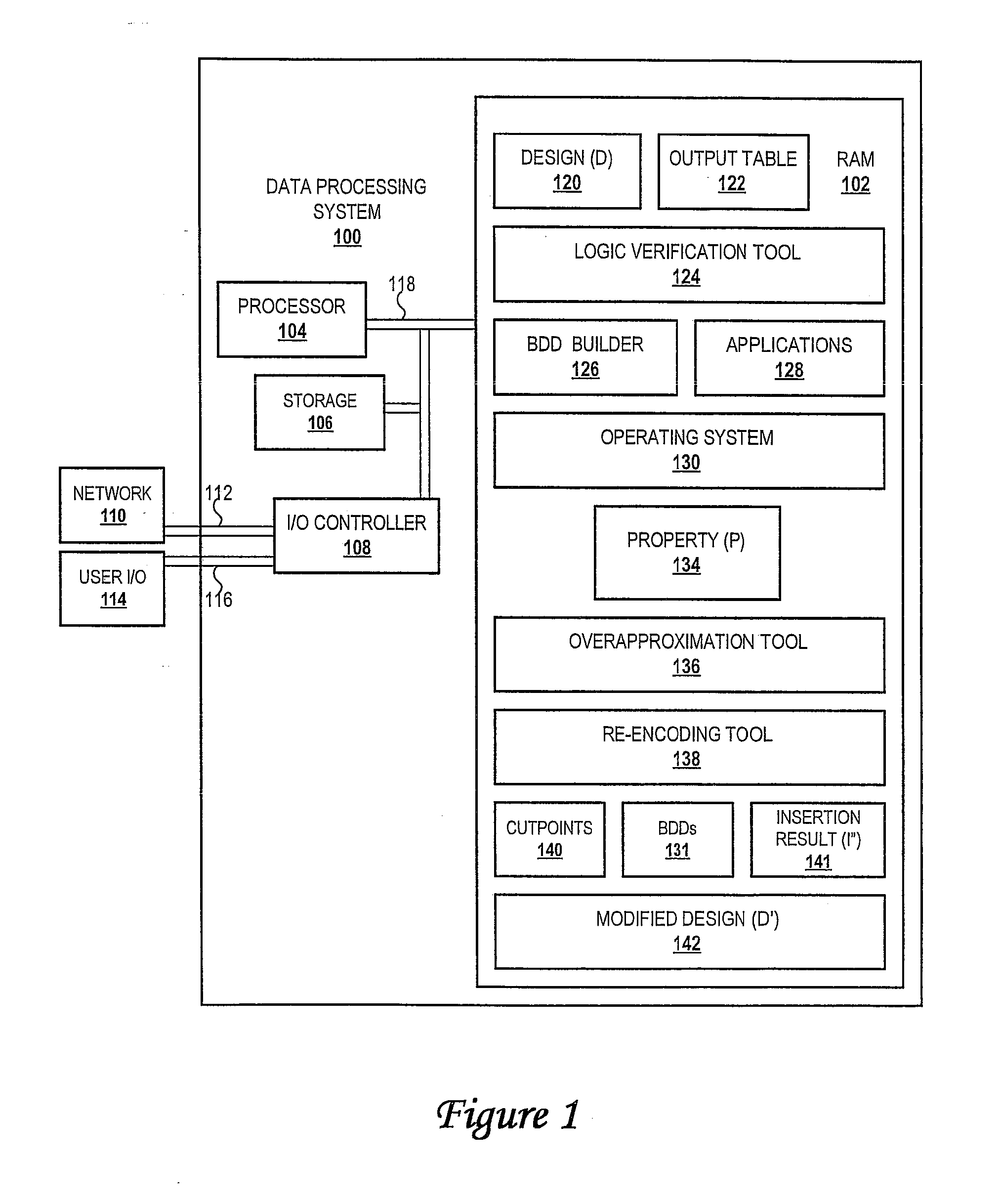
[0019]The present invention provides a novel synergistic transformation technique for reducing verification complexity. In particular, the present invention facilitates the synergistic use of a structural overapproximation technique for reducing the size of a sequential design, coupled with the use of a re-encoding technique to render additional property-preserving reductions. The benefit of this synergistic approach is that it enables design reductions far exceeding those possible in the prior art. The result of the present invention is drastic savings in computational resources for the verification process, enabling design flaws to be exposed and proofs to be completed that otherwise would be unfeasible.

[0020]The present invention relies upon the synergistic application of two techniques to yield increasing reductions of the design under test. First, a logic re-encoding technique simplifies the design under test while preserving its behavior. This re-encoding technique computes th...


PUM


Abstract

A method of incrementally reducing a design is disclosed. A logic verification tool receives a design and a property for verification with respect to the design, and then selects one or more of a plurality of diverse techniques for reducing the design. The logic verification tool then reduces the design to create a reduced design using the one or more techniques and attempts to generate a valid solution for the property on the reduced design. The logic verification tool determines whether a valid solution is generated, and, if not, replaces the design with the reduced design. Until a valid solution is generated, the logic verification tool iteratively performs the selecting, reducing, determining and replacing steps.

Description

PRIORITY CLAIM AND CROSS-REFERENCE TO RELATED APPLICATIONS[0001]The present application is a continuation of U.S. patent application Ser. No. 11 / 011,246, filed on Dec. 14, 2004, and entitled, “Method for Incremental Design Reduction Via Iterative Overapproximation and Re-Encoding Strategies, which also is related to U.S. Pat. No. 7,322,017 entitled “Method for Verification Using Reachability Approximation,” which are assigned to the assignee of the present invention and incorporated herein by reference.BACKGROUND OF THE INVENTION[0002]1. Technical Field[0003]The present invention relates in general to testing and verification, and in particular to verification of digital designs. Still more particularly, the present invention relates to a system, method and computer program product for incremental reduction of a digital design through iterative overapproximation and re-encoding.[0004]2. Description of the Related Art[0005]With the increasing penetration of processor-based systems in...

Claims


Application Information

Patent Timeline
Patent Type & Authority Applications(United States)
IPC IPC(8): G06F17/50
CPCG06F17/5045G06F30/30
Inventor BAUMGARTNER, JASON RAYMONDKANZELMAN, ROBERT LOWELLMONY, HARIPARUTHI, VIRESH
Owner GLOBALFOUNDRIES INC
Learn More