High-pressure mixing method and apparatus, with a self-lubricating and scraping device

a high-pressure mixing and scraping technology, applied in mechanical equipment, pressure lubrication, machines/engines, etc., can solve the problems of ineffective lubricating process, limited lubricating effect, and inability to ensure an even wetting, so as to prevent or reduce the formation of reacted materials, the effect of efficient and homogeneous lubricating and scraping action

Inactive Publication Date: 2008-06-05
AFROS
View PDF10 Cites 11 Cited by
  • Summary
  • Abstract
  • Description
  • Claims
  • Application Information

AI Technical Summary

Benefits of technology

[0016]The main object of the invention is to provide a method and a high-pressure mixing apparatus of the self-cleaning type, which makes use of the reciprocating movement of a cleaning member for cleaning the outlet duct for delivering of the reactive mixture and to carry out an efficient and homogeneous lubricating and scraping action; therefore it is to prevent or reduce the formation of deposits of reacted material on the inner surface of the outlet duct and the sticking of the cleaning member in the closed position of the same outlet duct.
[0017]A further object of this invention is to provide a mixing apparatus or device of the high-pressure type, provided with a self-lubricating device which exploits the reciprocating movement of the cleaning member for cleaning the outlet duct, to simultaneously carry out a scraping action of the reacted material as referred to above, and a pumping action for recirculating a lubricant capable of completely and evenly wetting the outlet duct, reducing any contact between opposite surfaces and at the same time achieving a highly efficient flushing action of the scraped particles of reacted material.
[0019]A still further object is to avoid or prevent the accumulation of scraped particles of reacted plastic material into the mixing apparatus, by flushing and entraining the scraped particles of reacted material which become detached from the inner surface of the outlet duct during the reciprocating movement of the cleaning member along the same duct.

Problems solved by technology

The intense frictional force caused by the reacted mixture, in addition to damaging the cleaning member, also requires the use of high-powered and large-sized hydraulic cylinders, with the consequent and well-known drawbacks and need for periodical maintenance operations for replacing the worn out parts.
While on the one hand, the use of a lubricating fluid according to the previously known solutions, tends to prevent the cleaning member from sticking to the outlet duct, and consequently reduce the frictional forces, on the other it does not ensure an even wetting and adequate entrainment of the lubricating fluid into contact with the entire surface of the outlet duct; the efficacy of lubrication in this way proves to be somewhat limited and ineffective.
Moreover, the repeated reciprocating movement of the cleaning member tends to entrain the particles of reacted material that become detached from the outlet duct, causing them to roll in the annular gap or slight clearance existing between facing surfaces of the cleaning member and the outlet duct, until they fill the lubricant chamber and cavities, thereby rendering the lubricating process ineffective.

Method used


Image

  • High-pressure mixing method and apparatus, with a self-lubricating and scraping device
  • High-pressure mixing method and apparatus, with a self-lubricating and scraping device
  • High-pressure mixing method and apparatus, with a self-lubricating and scraping device

Examples


Embodiment Construction

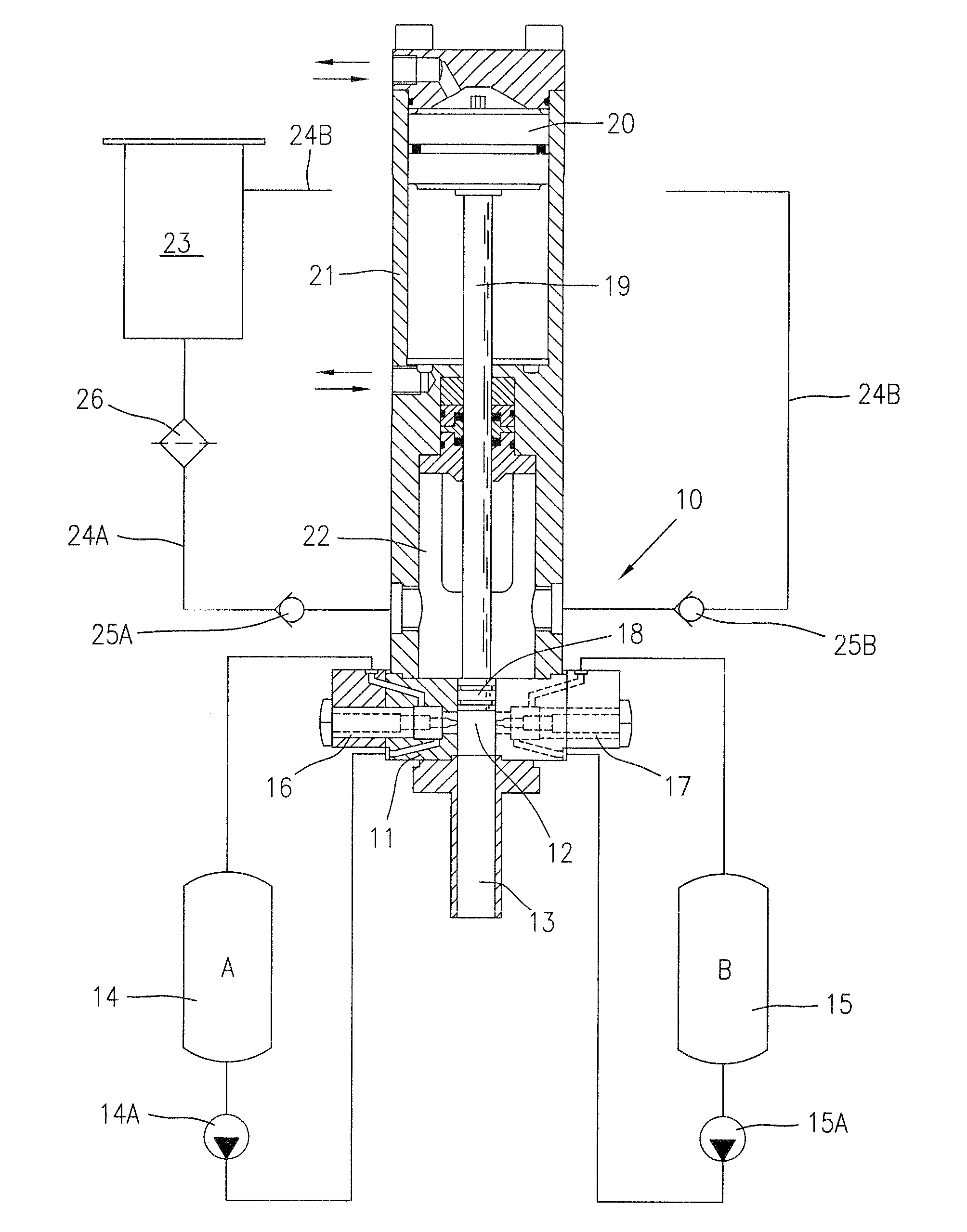
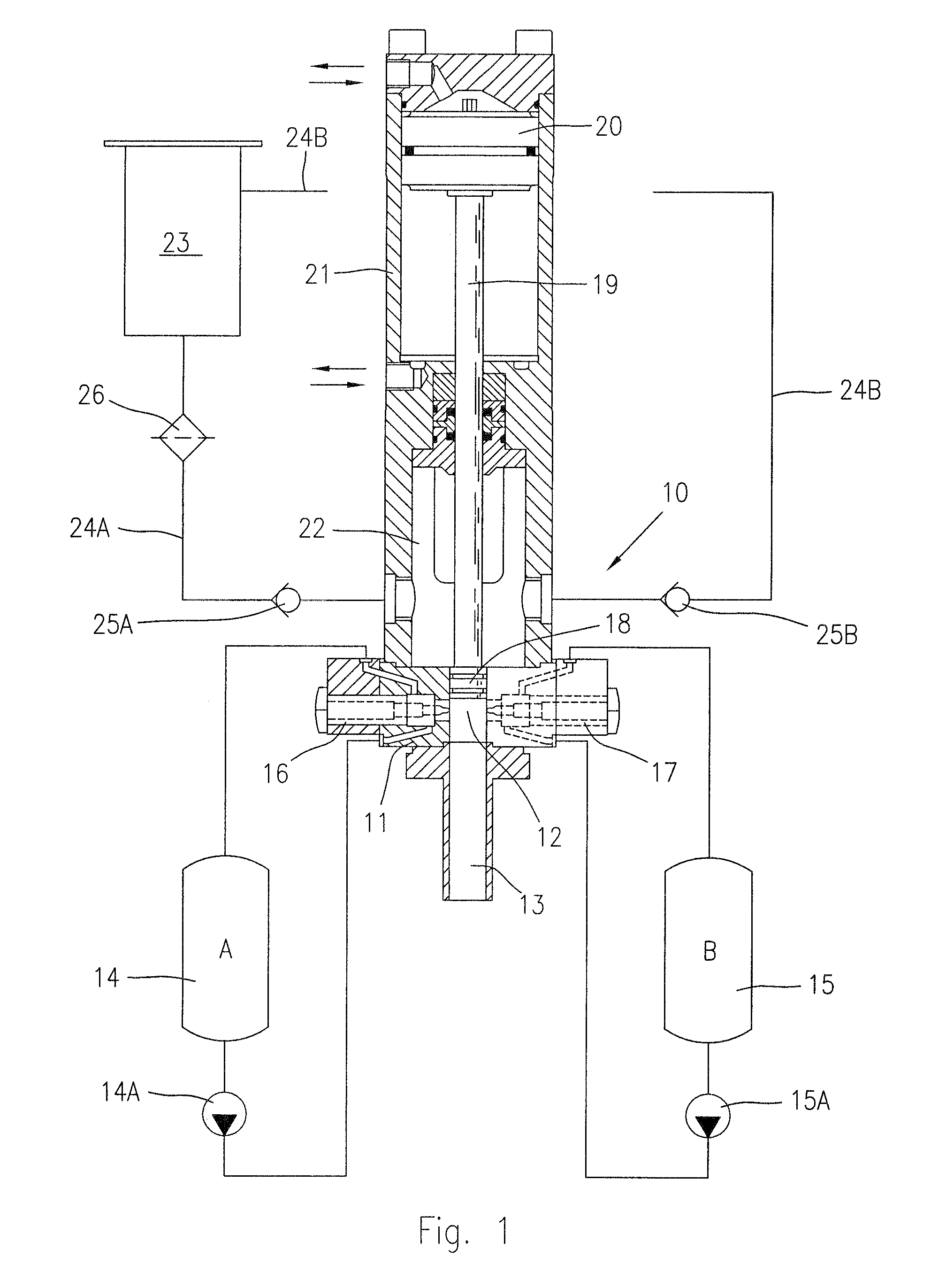
[0032]FIG. 1 shows a high-pressure self-cleaning mixing apparatus, of the linear type for mixing reactive chemical components into a resulting mixture, for example a polyol, an isocyanate and additives in the production of polyurethane foams and moulded articles.

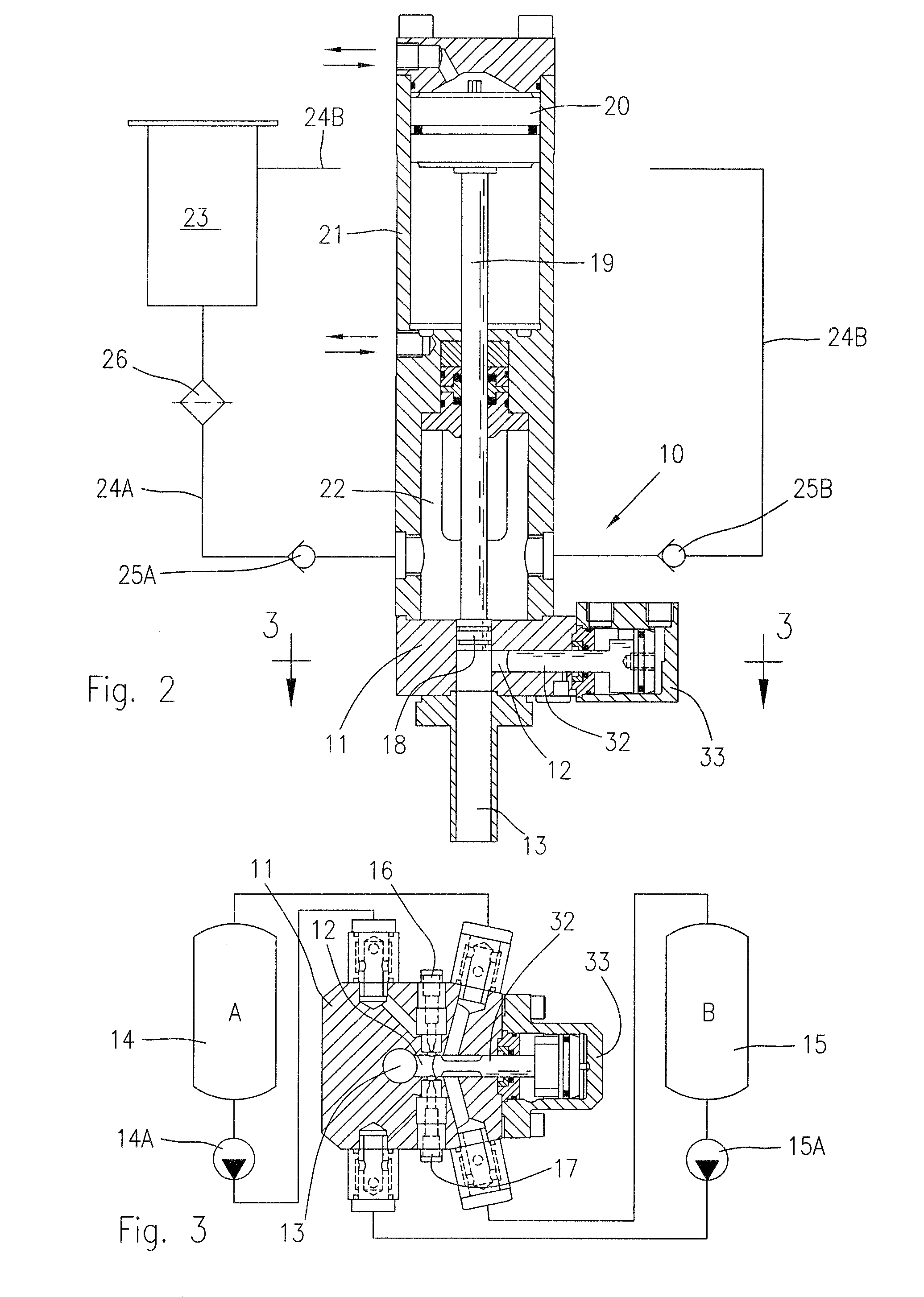
[0033]In the example shown, the mixing apparatus, indicated as a whole by reference number 10, comprises a body 11 having a mixing chamber 12 axially aligned to an outlet duct 13 for delivering a mixture resulting from at least two reactive chemical components A and B contained in respective storage tanks 14 and 15.

[0034]A first injector 16 connected to the tank 14 by a metering pump 14A, and a second injector 17 connected to the tank 15 by a metering pump 15A inject the components A and B which impinge and thoroughly mix together in the mixing chamber 12, according to a widely used and per se known technology.

[0035]The mixing apparatus 10 comprises a cleaning device for the outlet duct 13 substantially provided by a recipro...


PUM

PropertyMeasurementUnit
pressureaaaaaaaaaa
diameteraaaaaaaaaa
internal diameteraaaaaaaaaa

Abstract

The high-pressure mixing apparatus, for reactive chemical components, comprises a device for self-lubricating and scraping the outlet duct of the chemical mixture, and flushing out the scraped residues. The self-lubricating and scraping device comprises a delivery chamber for the lubricant material axially aligned and in fluid communication with the outlet duct; the lubricant delivery chamber is connected to a storage tank by a feeding and re-circulation circuit. The lubricant is sucked into the outlet duct and subsequently returned into the delivery chamber by a cleaning member in the form of a pumping piston sliding into the outlet duct, the pumping piston being provided with scraping rings for removing the reacted mixture adhered to the inner surface of the outlet duct.

Description

BACKGROUND OF THE INVENTION[0001]This invention refers to improvements to the high-pressure mixing apparatuses for mixing reactive chemical components; in particular the invention relates to a high-pressure mixing method for mixing reactive fluid polymeric components, such as a polyol and an isocyanate to form polyurethane mixtures, in which the action of a plunger or cleaning member is exploited to carry out a self-lubrication and recirculation of a lubricating fluid, to reduce the frictional forces, pre-venting the polymerisation and adhesion of the reacted mixture to the inner surface of an outlet duct.[0002]The invention also relates to a mixing apparatus or high pressure mixing head, of the aforementioned type, comprising a reciprocable cleaning member or plunger for cleaning the outlet duct by ejecting the resulting mixture, in which the plunger is conformed for scraping and causing a recirculation of a lubricant for the outlet duct.STATE OF THE ART[0003]A mixing apparatus for...

Claims


Application Information

Patent Timeline
Patent Type & Authority Applications(United States)
IPC IPC(8): F16N39/08F01M1/04
CPCB29B7/7684B29B7/7663B29B7/7689B29B7/7694B29C67/246B29B7/7404B29B7/805B29B7/7615B29B7/7668
Inventor FIORENTINI, CARLOCORTI, MAURIZIO
Owner AFROS
Why Eureka
Try Eureka