
Heated Spray Painting System

a spray painting and spraying technology, applied in the direction of heating apparatus, heating element shapes, lighting and heating equipment, etc., can solve the problems of long drying time, excessive difficulty in reducing so as to reduce the drying time of spray pain

Inactive Publication Date: 2008-06-05
EUROSIDER S DI MILLI OTTAVIO & C
View PDF24 Cites 7 Cited by
  • Summary
  • Abstract
  • Description
  • Claims
  • Application Information

AI Technical Summary

Benefits of technology

[0007]Therefore the need is strongly felt for a device which provides the spray painting system with a hot flow irrespective of the distance between the source and the user device and therefore a pressurised hot carrier fluid (for example dried air or nitrogen) able to drastically reduce the drying times of the paint applied.
[0010]A first advantage is that the drying time is cut from the current 15-40 minutes to times which vary from one minute to 5 minutes with the system disclosed, particularly in the case of spray painting with water- or solvent-based paints, irrespective of the distribution of the painting points relative to the source of the carrier fluid, and also irrespective of the availability of a source of carrier fluid that is already hot.

Problems solved by technology

It is known that in the painting sector in general and in particular for spray painting, the paint is mixed with a carrier fluid commonly consisting of compressed air but also modified nitrogen-rich air, and that the drying times for the coats of paint applied are often excessively long partly due to the humidity present in the fluid used as the carrier and / or in the painting environment and absorbed by the carrier fluid and by the components to be painted.
In particular, the length of the paint drying time is a problem felt in water-based painting systems, increasingly used due to their low environmental impact and greater safety, but which at the same time use water as a solvent, necessitating longer drying times.
This disadvantage is particularly felt where the distance between the apparatus which produces the carrier fluid and the point of use is great, the consequence being that any heating of the fluid at the source is lost and does not provide effects useful for its use.

Method used


Image

  • Heated Spray Painting System
  • Heated Spray Painting System
  • Heated Spray Painting System

Examples


Embodiment Construction

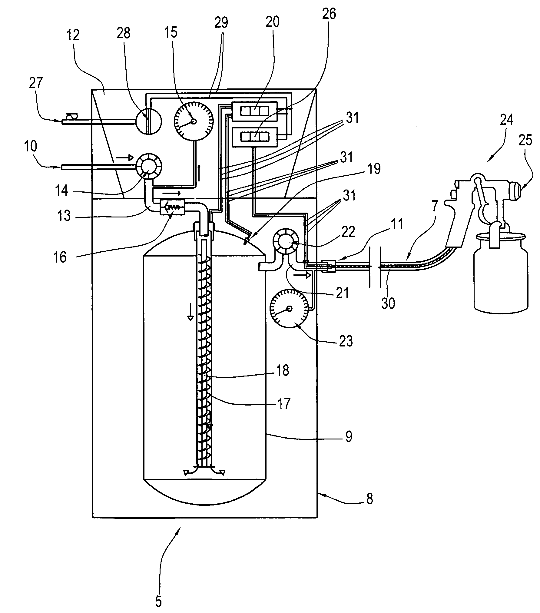
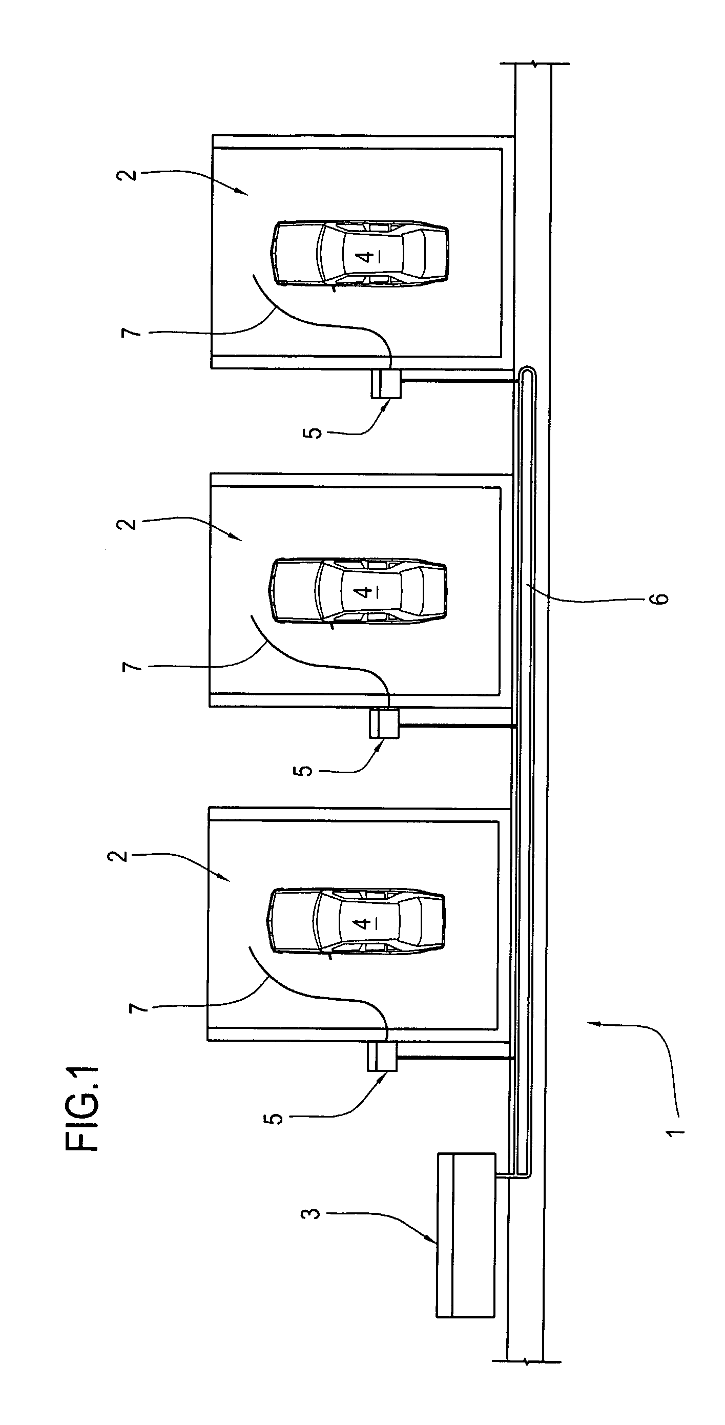
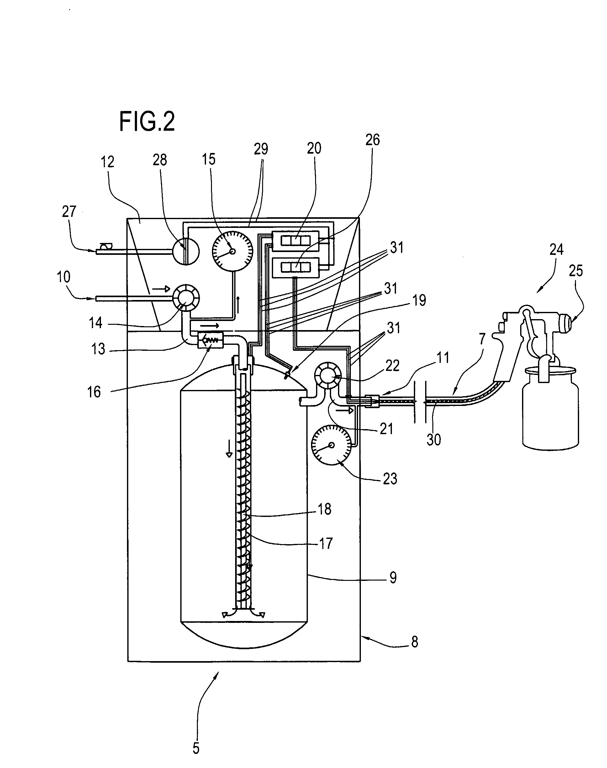
[0014]FIGS. 1 and 2 are schematic illustrations of a painting system and a heater in accordance with the invention.

[0015]With reference to FIG. 1, a painting system 1 is described having a plurality of local painting stations 2 and a feed 3 of carrier fluid for use in spray painting an object, for example motor cars 4.

[0016]According to the invention, attached to each station 2 there is a device 5 for heating the carrier fluid, individually connected to the feed 3 by a distribution unit 6, preferably ring-shaped, so as to make the pressure at each heater 5 uniform.

[0017]Each heater 5 may also have a flexible tube 7 at its outlet, preferably being equipped with heating means 30, positioned inside or outside at least one portion of the tube.

[0018]In the layout in FIG. 1, there are three stations 2 and the same number of heaters 5 attached to them, but it shall be understood that the number of stations in the system, like the number of feeds 3 and heaters 5 attached to one or more stat...


PUM


Abstract

A system and device for spray painting using a flow of pressurised carrier fluid comprises a central source of the carrier fluid and one or more local elements for heating the fluid close to the point of use.

Description

TECHNICAL FIELD[0001]The present invention relates to a spray painting system, beginning with a carrier fluid consisting of compressed air, modified nitrogen-rich air or another suitable fluid.BACKGROUND ART[0002]It is known that in the painting sector in general and in particular for spray painting, the paint is mixed with a carrier fluid commonly consisting of compressed air but also modified nitrogen-rich air, and that the drying times for the coats of paint applied are often excessively long partly due to the humidity present in the fluid used as the carrier and / or in the painting environment and absorbed by the carrier fluid and by the components to be painted.[0003]The level of humidity is also increased by the expansion of the fluid, when the distance between the pressurised source and the user device is particularly long, for example more than one metre.[0004]To reduce drying times at present the use of both hot dried air and further measures such as the use of volatile solv...

Claims


Application Information

Patent Timeline
IPC IPC(8): B05B9/00
CPCB05B15/1207B05B7/162B05B16/20
Inventor MILLI, OTTAVIO
Owner EUROSIDER S DI MILLI OTTAVIO & C
Learn More