Motor

a motor and motor technology, applied in the direction of windings, magnetic circuit rotating parts, magnetic circuit shape/form/construction, etc., can solve the problems of increasing the increasing the international demand for copper occasionally, and affecting the production efficiency of the motor, so as to reduce the production cost of the motor, reduce the cost of the coil in the motor, and facilitate manufacturing

Active Publication Date: 2008-06-05
LG ELECTRONICS INC
View PDF11 Cites 34 Cited by
  • Summary
  • Abstract
  • Description
  • Claims
  • Application Information

AI Technical Summary

Benefits of technology

[0010]An advantage of the present invention is that the cost of a coil in a motor can be reduced and to provide a motor that may reduce the production cost of a motor on the whole.
[0011]Another advantage of the present invention is to provide a motor that is easy to fabricate, enhances reliability, and has a long lifetime
[0012]Additional features and advantages of the invention will be set forth in the description which follows, and in part will be apparent from the description, or may be learned by practice of the invention. The objectives and other advantages of the invention will be realized and attained by the structure particularly pointed out in the written description and claims hereof as well as the appended drawings.
[0013]To achieve these and other advantages and in accordance with the purpose of the present invention, as embodied and broadly described, a motor includes: a stator having a stator core; an insulator attached to the stator core for winding a coil thereon; a rotor; and a tap terminal provid

Problems solved by technology

However, the high costs of copper tends to increase the cost of the motor.
Moreover, because of the a lack of a stable

Method used


Image

  • Motor
  • Motor
  • Motor

Examples


Embodiment Construction

[0031]Reference will now be made in detail to an embodiment of the present invention, example of which is illustrated in the accompanying drawings.

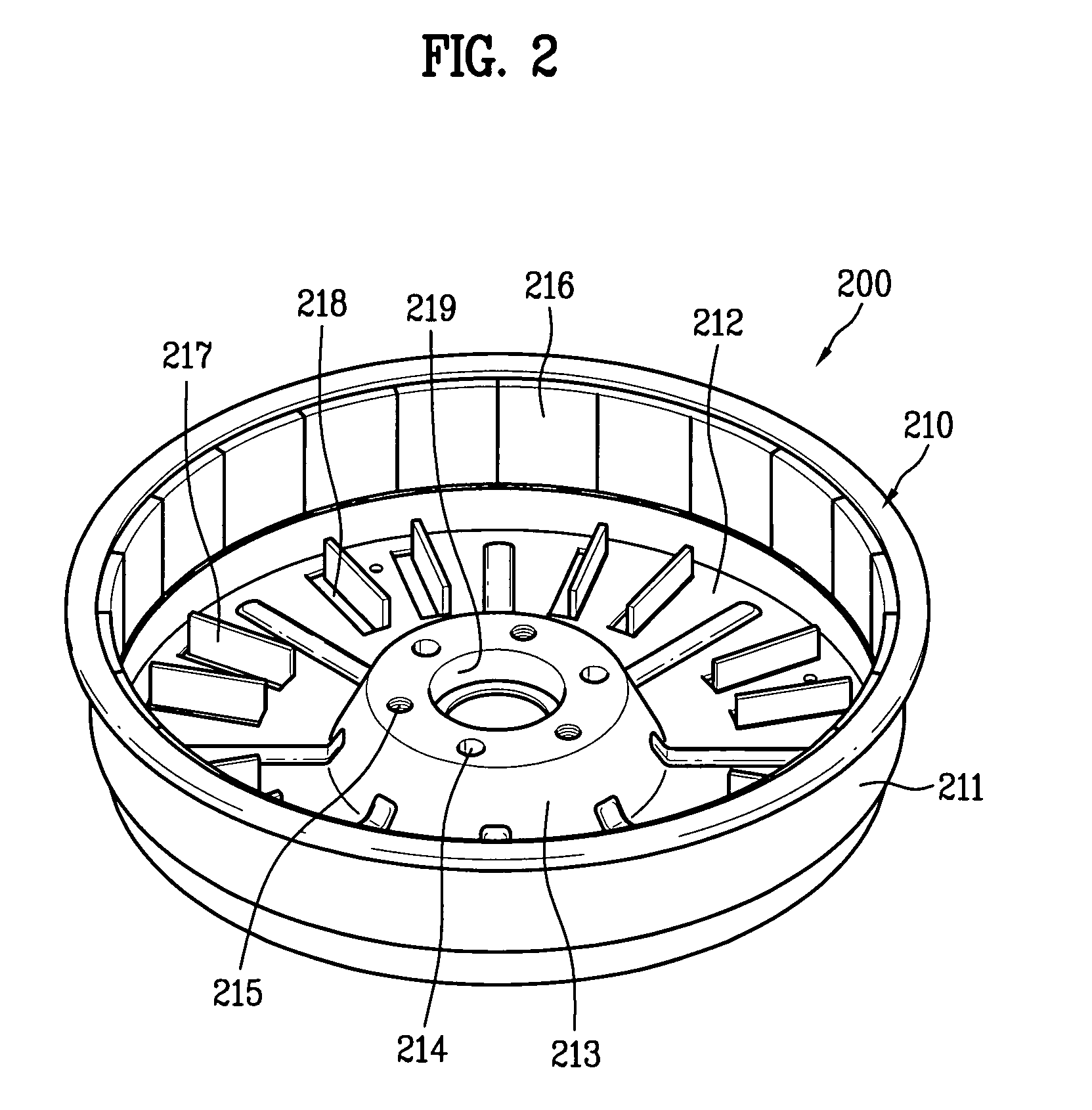
[0032]A structure of a motor in accordance with a preferred embodiment of the present invention will be described with reference to FIGS. 1 and 2.

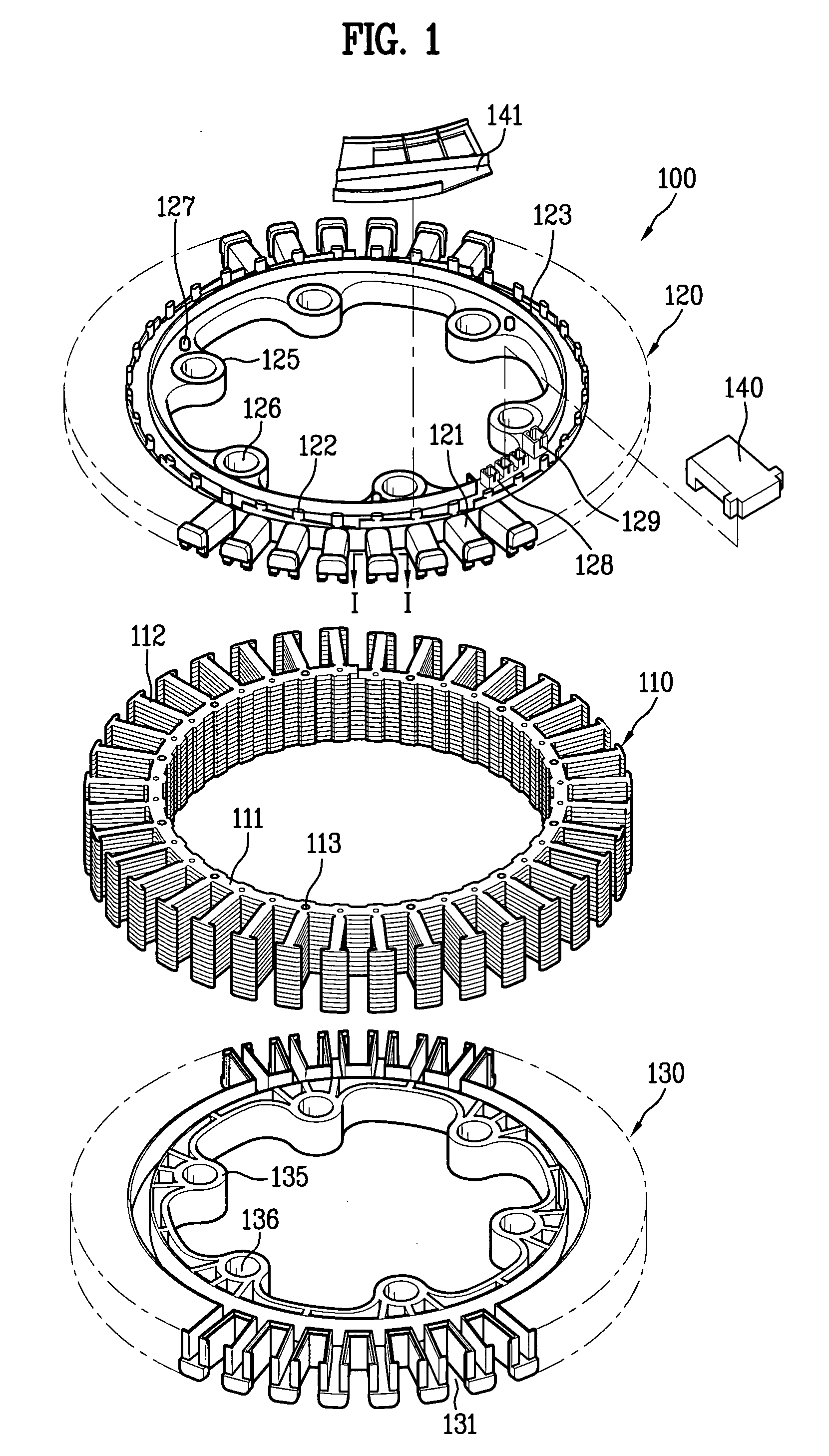
[0033]FIG. 1 is an exploded perspective view illustrating a stator of a motor in accordance with an embodiment of the present invention.

[0034]Referring to FIG. 1, the stator 100 includes a stator core 110, an upper insulator 120, and a lower insulator 130.

[0035]The stator core 110 has an annular back yoke 111 and T-shaped projections 112 each projected outward in a radial direction from an outside circumference of the back yoke 111. FIG. 1 illustrates a stator 100 of an outer rotor type motor having a rotor provided to an outer side of the stator core. Accordingly, the T-shaped projections 112 may be projected inwardly in a radial direction from an inside circumference of the back yoke. In this ...


PUM


Abstract

The motor including a stator having a stator core, and an insulator provided to the stator core for winding a coil thereon, a rotor rotatably provided with respect to the stator, and a tap terminal provided to the insulator for positioning an end of the coil, wherein the coil includes a core wire of aluminum.

Description

[0001]This application claims the benefit of the Patent Korean Application Nos. 10-2006-0120657, 0120658, and 0120659, all of which were filed on Dec. 1, 2006, and are hereby incorporated by reference as if fully set forth herein.BACKGROUND OF THE INVENTION[0002]1. Field of the Invention[0003]The present invention relates to motors, and more particularly, to a motor which reduces production costs and can enhance productivity and reliability.[0004]2. Discussion of the Related Art[0005]In general, a motor transmits rotating force of a rotor to a rotating shaft which drives a load. For example, the rotating shaft can drive a drum of a washing machine, or a refrigerator fan connected thereto for supplying cold air to a required space.[0006]Also, inside the motor the rotor rotates in an electromagnetic interaction with a stator. For this, the stator has coils wound thereon and, upon application of a current, the rotor rotates with respect to the stator.[0007]Typically, the coil is formed...

Claims


Application Information

Patent Timeline
IPC IPC(8): H02K11/00
CPCH02K1/187H02K3/02H02K3/18H02K29/08H02K3/522H02K15/00H02K3/44
Inventor SHIN, SUNG YONGBYUN, JEONG UKKIM, SUNG JUNG
Owner LG ELECTRONICS INC
Why Eureka
Try Eureka