Method and apparatus employing multi-functional controls and displays

a multi-functional control and display technology, applied in the field of flat panel based control system interfaces, can solve the problems of d work, no one allows any reconfiguration of classical controls such as knobs and switches, parallax and other reading problems, etc., and achieve the effect of low cos

Inactive Publication Date: 2008-06-05
APPLE INC
View PDF100 Cites 120 Cited by
  • Summary
  • Abstract
  • Description
  • Claims
  • Application Information

AI Technical Summary

Benefits of technology

[0024]The availability of dependable and low costs camera systems in the vehicle for human interface purposes leads as well to disclosed embodiments herein for games and other entertainment which can be played on trips or the like

Problems solved by technology

All of these approaches have significant disadvantages, and none allows any reconfiguration of classical controls such as knobs and switches most familiar to the vast majority of the motoring public.
However substantial projection display and machine vision R and D work is required to meet cost targets for its intended primary automotive instrument panel application.
This approach has the disadvantage that the use of an overlay member and the base member makes the knob stick up higher off the screen which can be aesthetically displeasing, and results in parallax and other reading problems of seeing the programmably reconfigurable lettering or other labeling on the screen adjacent the knob, or within the knob if it transparent, or slotted as I have disclosed.
An other problem exists if one then wishes to locate a conventional touch screen sensing member (e.g., such as made by 3M company) underneath the knob and in front of the screen, in which case the problem is accentuated, and in the Jaeger et al invention also made more difficult because the base member must then attach to the touch screen.
In addition the base member and knob must be of a special design, adding cost.
Unlike my hitherto disclosed RTD invention, which in preferred embodiments uses a projection display, the LCD flat panel displays become considerably more costly as the display size rises.
In addition flat panels become uglier to look at due to their flat nature.
Thus it is likely that LCD screens in cars will be limited in size, and thus space on their display area will be at a premium.
The large flat glass front piece of an LCD screen can pose a safety hazard as well.
It should also be pointed out that the Jaeger et al knob disclosure deals only with sensing knob position, and does not allow for using the knob to switch high current devices, for example to provide for direct switching of currents to motors in the vehicle.

Method used


Image

  • Method and apparatus employing multi-functional controls and displays
  • Method and apparatus employing multi-functional controls and displays
  • Method and apparatus employing multi-functional controls and displays

Examples


Embodiment Construction

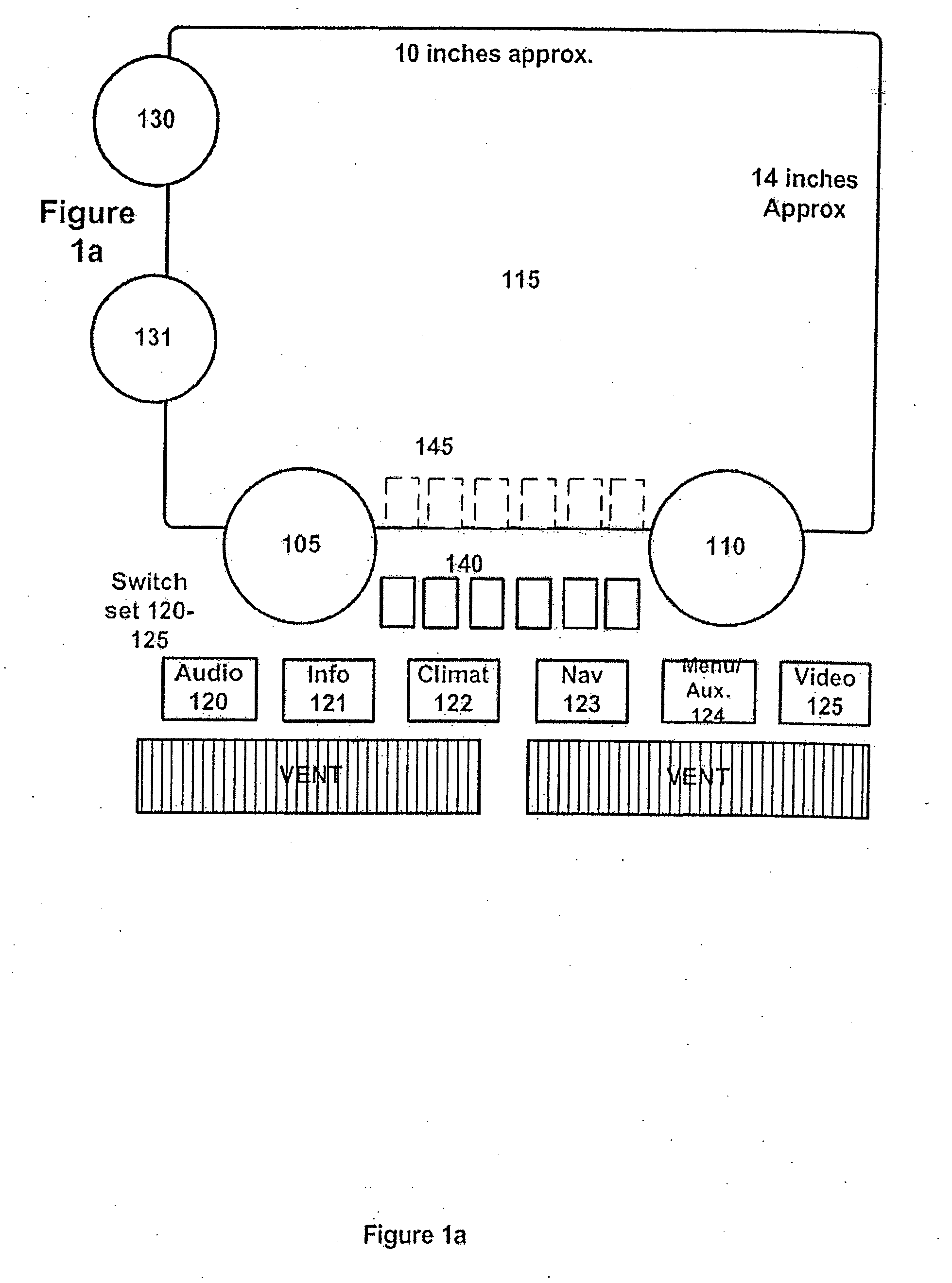
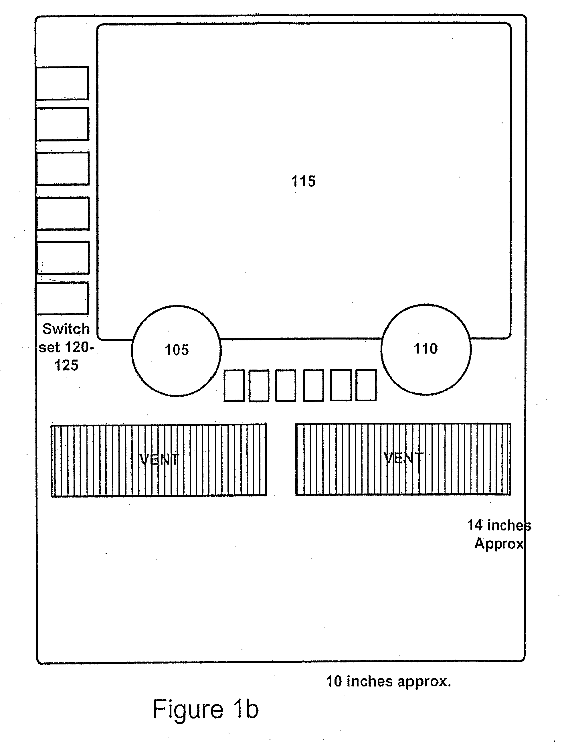
[0048]FIG. 1a is a front view of a basic embodiment of the invention, located in the “center stack”, 100, of a vehicle instrument panel. A typical center stack is approximately 10 inches wide and 14 inches high, though dimensions may vary from top to bottom (where the center console or transmission hump is), and other cars or trucks may have different dimensions. As shown the air vents commonly found at the top of the center stack have been moved to the middle, to allow for putting the most display area as close to the drivers line of sight as possible. The display in FIG. 1 is blank, with the system turned off. Examples of it “on” for different selected functions on are given below.

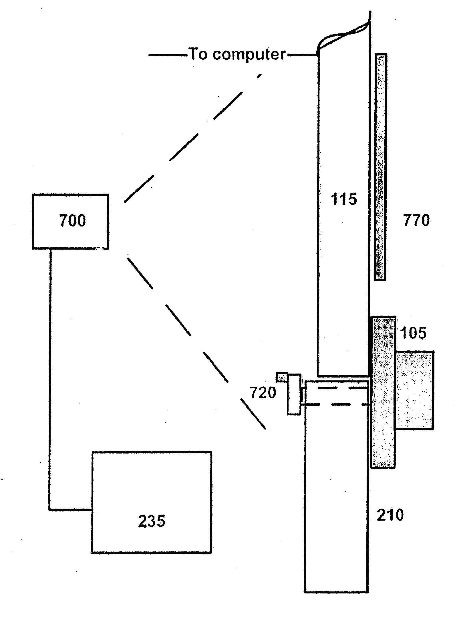
[0049]Two knobs having reconfigurable functions, 105 and 110 overlap a standard flat panel display 115, (in this case a large LCD type having a width of 9.3 inches and a height of 6.2 inches, with a diagonal measurement of 11 inches—double the area of the 8 inch screens which are the maximum used today)....


PUM


Abstract

Methods and apparatus are disclosed video displays that can sense finger, object or other control information proximate the display face. Electro-optical sensing is general employed, though some embodiments illustrate conventional electronic means. Diverse applications to vehicles, homes and control systems and the like are discussed.

Description

CROSS REFERENCE TO RELATED APPLICATIONS[0001]This application is a continuation of Ser. No. 11 / 184,076 filed Jul. 19, 2005; which claims benefit of U.S. provisional applications 60 / 591,213, (Multifunctional Control Systems), filed Jul. 27, 2004, and 60 / 598,446 (Flat Panel Based Control Devices), filed Aug. 4, 2004. The disclosures of these applications are hereby incorporated by reference.[0002]The disclosures of U.S. Pat. Nos. 5,982,352 and 5,372,970, by the inventor, are incorporated in their entirety along with an SAE paper entitled Reconfigurable Tactile Control Displays, co-authored by the inventor, which was presented at the Convergence 2004 Conference in Detroit, Mich. in October, 2004.FIELD OF THE INVENTION[0003]The invention herein primarily concerns flat panel based control system interfaces which have certain commonality with my “Reconfigurable Tactile Control Display” (RTD) invention described in co-pending references, particularly in the method of sensing knobs (and oth...

Claims


Application Information

Patent Timeline
Patent Type & Authority Applications(United States)
IPC IPC(8): G06F3/042
CPCG06F3/0304G06F3/0425G06F3/0312
Inventor PRYOR, TIMOTHY R.
Owner APPLE INC
Why Eureka
Try Eureka