
Switch mode power supply and driving method thereof

a power supply and switching mode technology, applied in the direction of electric variable regulation, process and machine control, instruments, etc., can solve the problems of low switching voltage, low switching voltage, and low switching frequency, and achieve the effect of reducing the noise in the audible frequency range and the switching loss

Active Publication Date: 2008-06-05
SEMICON COMPONENTS IND LLC
View PDF12 Cites 102 Cited by
  • Summary
  • Abstract
  • Description
  • Claims
  • Application Information

AI Technical Summary

Benefits of technology

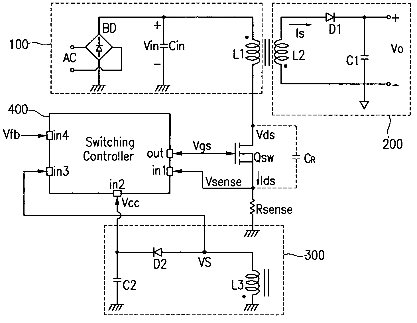
[0013]Briefly and generally, embodiments of the present invention include an SMPS and a driving method thereof having the advantage of reducing a switching loss and a noise in the audible frequency range.
[0016]The switch controller counts the switching operations of the main switch by using the gate signal for controlling the on / off state of the main switch during the switching operation on period, and the switch controller prevents the switching operation of the main switch during the switching operation forcibly off period when the switching operation on period is finished.

Problems solved by technology

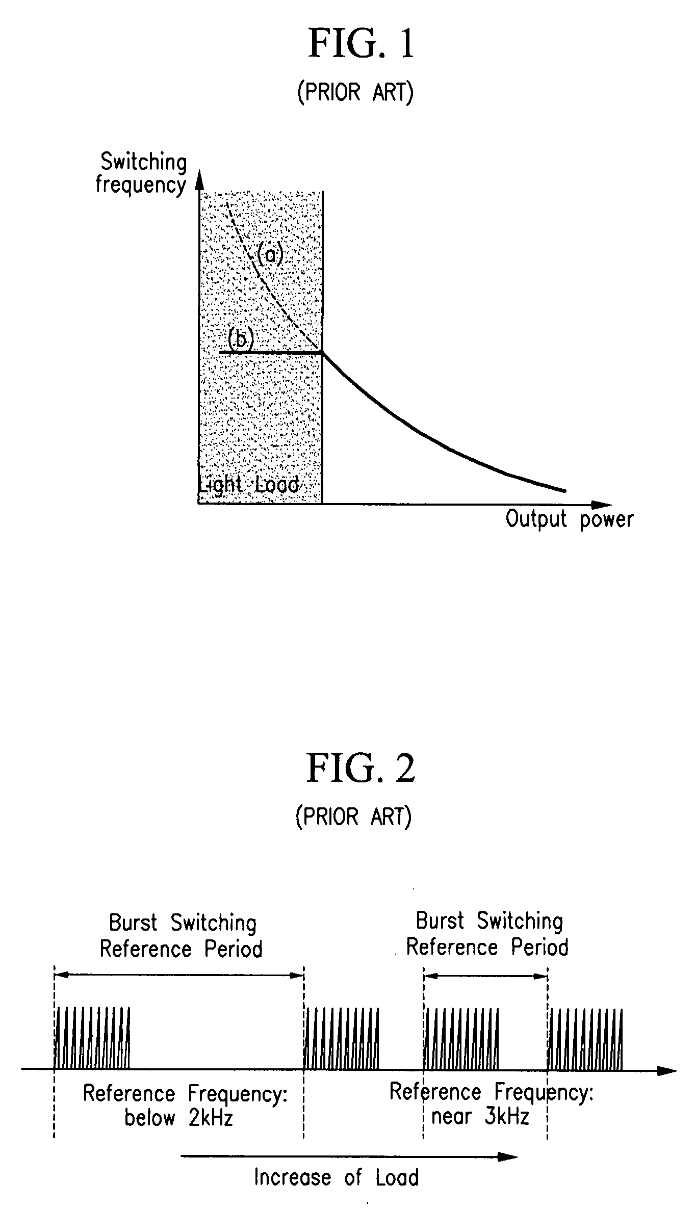
The increase of the switching frequency under light load condition generates a switching loss.
However, when the switching frequency of the main switch is restricted to a predetermined value, it is a challenge to perform switching at the lowest switch voltages.
This non-optimal operation at low switching voltages is disadvantageous and leads to a switching loss.
This switching loss is also enhanced in the case of a large input voltage.
In this normal mode operation of the SMPS the frequency of the noise may move into the 2-3 kHz frequency range, which is audible to the user, which is undesirable.

Method used


Image

  • Switch mode power supply and driving method thereof
  • Switch mode power supply and driving method thereof
  • Switch mode power supply and driving method thereof

Examples


Embodiment Construction

[0039]In the following detailed description, only certain exemplary embodiments of the present invention are shown and described, simply by way of illustration. As those skilled in the art will realize, the described embodiments may be modified in various different ways, all without departing from the spirit or scope of the present invention. Accordingly, the drawings and description are to be regarded as illustrative in nature and not restrictive. Like reference numerals designate like elements throughout the specification.

[0040]Throughout this specification and the claims that follow, when it is described that an element is “coupled” to another element, the element may be “directly coupled” to the other element or “electrically coupled” to the other element through one or more additional elements.

[0041]A quasi-resonant converter and an SMPS using it will now be described with reference to the drawings. The switching operation represents an operation in which a main switch is turne...


PUM


Abstract

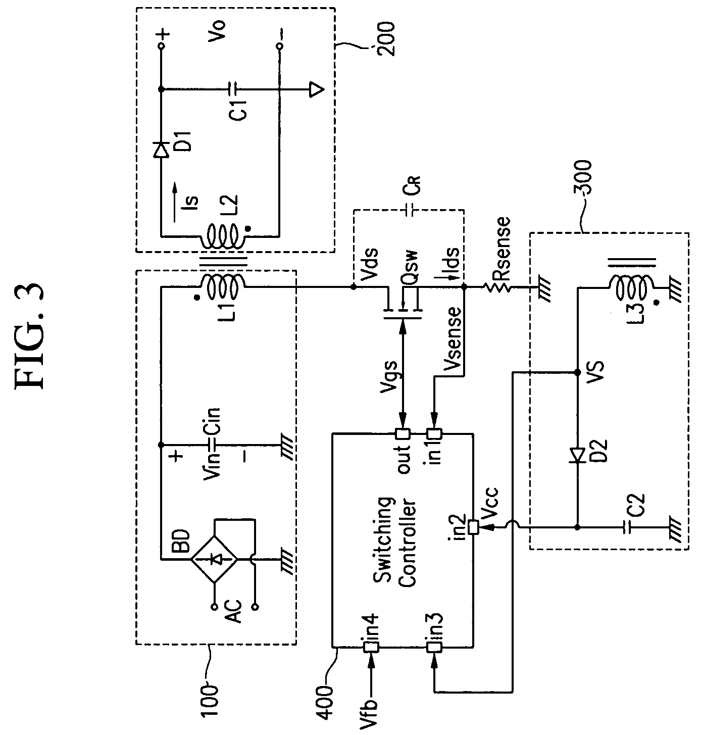
The present invention relates to a switch mode power supply and a driving method for reducing switching loss and audible noise in the burst mode. The switch mode power supply includes a main switch, a power supply, an output unit, and a switch controller. The power supply includes a transformer having a primary coil connected to the main switch, and supplies power to a secondary coil of the transformer according to the operation of the main switch. The output unit is connected to the secondary coil of the transformer and outputs power supplied to the secondary coil of the transformer. The switch controller receives a feedback signal corresponding to the output voltage of the output unit, a sense signal corresponding to the current flowing to the main switch, and a sync signal corresponding to the voltage difference at the main switch, controls the on / off of the main switch, and determines whether to start the burst mode by using the feedback signal, and maintains the switching operation forcibly off period in the burst mode so that the reference frequency of burst switching may be less than a predetermined value.

Description

CROSS-REFERENCE TO RELATED APPLICATION[0001]This application claims priority to and the benefit of Korean Patent Application No. 10-2006-0119726 filed in the Korean Intellectual Property Office on Nov. 30, 2006, the entire content of which is incorporated herein by reference.BACKGROUND[0002]1. Field of the Invention[0003]The present invention relates to a switch mode power supply (SMPS). More particularly, the present invention relates to a quasi-resonant switching type SMPS and a driving method thereof.[0004]2. Description of the Related Art[0005]An SMPS is a device for rectifying an input AC voltage into an input DC voltage (dc-link voltage) and converting the input DC voltage into a DC output voltage having a different level. The DC output voltage can be greater than or equal to the input DC voltage. The SMPS is generally used for battery power supplies that power electronic devices, and particularly, mobile terminals or laptop computers.[0006]The quasi-resonant switching mode ba...

Claims


Application Information

Patent Timeline
Patent Type & Authority Applications(United States)
IPC IPC(8): H02M3/335H02M7/04
CPCH02M3/33507Y02B70/16Y02B70/1433H02M2001/0032H02M1/0032Y02B70/10H02M3/28
Inventor CHOI, HANG-SEOKCHI, JAE-HWOAN
Owner SEMICON COMPONENTS IND LLC
Learn More