Variable-mode converter control circuit and half-bridge converter having the same

a control circuit and converter technology, applied in the direction of automatic control, process and machine control, instruments, etc., can solve the problems of increasing the size and manufacturing cost of the system, the smallness and lightness of the power supply indispensable to such electronic appliances, and the need for small and light power supplies

Active Publication Date: 2008-06-05
SEMICON COMPONENTS IND LLC
View PDF12 Cites 16 Cited by
  • Summary
  • Abstract
  • Description
  • Claims
  • Application Information

AI Technical Summary

Benefits of technology

[0024]In some embodiments, the switching controller comprises: an oscillating unit for generating a pulse signal and triangle-wave signal of a certain frequency; a switching control signal output unit for outputting the switching control signal to control the switching operation of the switching circuit based on a duty ratio determined from the feedback signal, the feedback signal being applied from the feedback circuit to a feedback terminal; a mode select signal generator for generating a mode select signal for determination of a control mode of the converter in response to the feedback signal applied to the feedback terminal; and a mode selecting unit for selecting the control mode in response to the mode select signal.
[0025]In some embodiments, the switching controller further comprises an RT terminal, a CT terminal, and the feedback terminal, wherein the switching control signal output unit and the mode select signal generator are connected in common with the feedback terminal.
[0026]In some embodiments, the switching control signal output un

Problems solved by technology

Further, the smallness and lightness of power supplies indispensable to such electronic appliances have also been required.
For this reason, where a system uses different converters, it must have different control circuits based on the used converters, resulting in the occurrence of various problems including increases in the size and manufacturing cost of the system.

Method used


Image

  • Variable-mode converter control circuit and half-bridge converter having the same
  • Variable-mode converter control circuit and half-bridge converter having the same
  • Variable-mode converter control circuit and half-bridge converter having the same

Examples


Embodiment Construction

[0036]Embodiments of the present invention will now be described in detail with reference to the accompanying drawings. The embodiments of the present invention have been disclosed for illustrative purpose only and should not be construed as limiting the scope of the present invention.

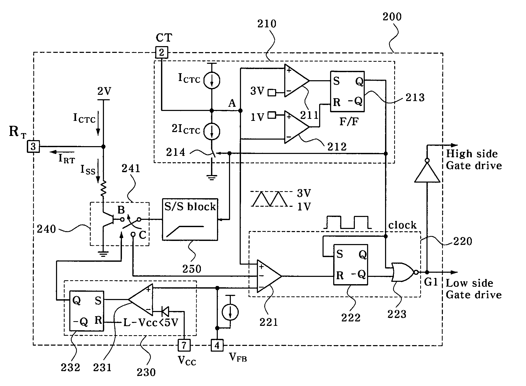
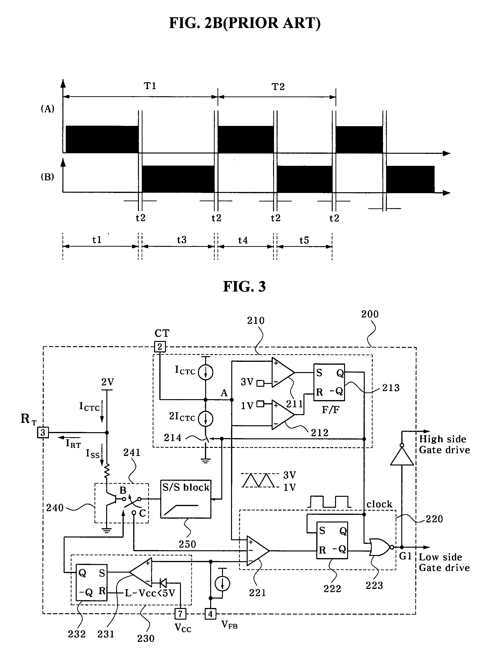
[0037]FIG. 3 is a circuit diagram of a variable-mode converter control circuit 200 according to an embodiment of the present invention.

[0038]The variable-mode converter control circuit 200 may comprise an oscillator 210 for generating a pulse signal and a triangle-wave signal of a certain frequency, a switching control signal output unit 220 for outputting a switching control signal to turn ON / OFF of a plurality of switching devices based on a duty ratio determined from a feedback signal Vfb, which is applied to a feedback terminal VFB, a mode select signal generator 230 for generating a mode select signal for determination of a control mode of a converter in response to the feedback signal Vfb applied...


PUM


Abstract

A converter control circuit applicable to various topologies of converters each employing two switching devices is disclosed. The converter control circuit includes an oscillator for generating a pulse signal and triangle-wave signal of a certain frequency, a switching control signal output unit for outputting a switching control signal to control ON / OFF of a plurality of switching devices based on a duty ratio determined from a feedback signal which is applied to a feedback terminal, a mode select signal generator for generating a mode select signal for determination of a control mode of a converter in response to the feedback signal applied to the feedback terminal, and a mode selecting unit for selecting the control mode in response to the mode select signal.

Description

CROSS-REFERENCE TO RELATED APPLICATION[0001]This application claims priority and the benefit of Korean Patent application No. 10-2006-0122421, filed in the Korean Intellectual Property Office on Dec. 5, 2006, the entire content of which is incorporated herein by reference.BACKGROUND[0002]1. Field of the Invention[0003]The present invention relates to a converter control circuit and a converter having the same, and more particularly to a converter control circuit which is capable of changing an operation mode, and a half-bridge converter having the same.[0004]2. Description of the Related Art[0005]Recently, with the advance of electronic appliances, integrated circuit (IC) technologies have been utilized in these appliances to improve their performance while making their size and weight small. Further, the smallness and lightness of power supplies indispensable to such electronic appliances have also been required. Switched mode power supplies are mainly used as stabilized power supp...

Claims


Application Information

Patent Timeline
IPC IPC(8): H02M3/335H02M3/22
CPCY02B70/1433H02M3/3376Y02B70/10H02M7/53846H02M7/5387
Inventor CHOI, HANG SEOK
Owner SEMICON COMPONENTS IND LLC
Why Eureka
Try Eureka