Method and system for forwarding ethernet frames over redundant networks with all links enabled

a network and ethernet frame technology, applied in the field of redundant network configurations, can solve the problems of inability to see how reliable discrimination could be achieved, inability to implement packet recognition, etc., and achieve the effect of reducing the lifetime of node location information learned

Inactive Publication Date: 2008-06-05
KAEMPFER GIDEON
View PDF13 Cites 17 Cited by
  • Summary
  • Abstract
  • Description
  • Claims
  • Application Information

AI Technical Summary

Benefits of technology

[0014]Network nodes suppress traffic from traveling in loops by identifying and dropping recurring frames within a given (typically short) timeframe based on a set of increasingly significant tests enabling the identification of such frames using very low memory resources.
[0016]In some embodiments of the present invention in the event of network topology changes such as a link failure or recovery, nodes forward topology change notifications to their neighbors to clear or reduce the lifetime of node location information learned, and to enable correct learning of updated information based on the new network topology.
[0017]Ethernet switching devices such as Ethernet switches may be implemented to use the above methods as an integral part of their functionality in data networks. An alternate embodiment of the present invention may use complementary systems that may implement methods of the present invention. Such complementary systems may be deployed in adjacency to standard Ethernet switches and control the Ethernet switches according to the dynamics of the network. Embodiments of the present invention enable the switches to perform shortest path forwarding in a redundant network where all links are enabled.

Problems solved by technology

It is difficult to see how sufficiently reliable discrimination could be achieved without some form of per-router signature such as route recording.
A packet recognizing approach therefore seems infeasible.”

Method used


Image

  • Method and system for forwarding ethernet frames over redundant networks with all links enabled
  • Method and system for forwarding ethernet frames over redundant networks with all links enabled
  • Method and system for forwarding ethernet frames over redundant networks with all links enabled

Examples


Embodiment Construction

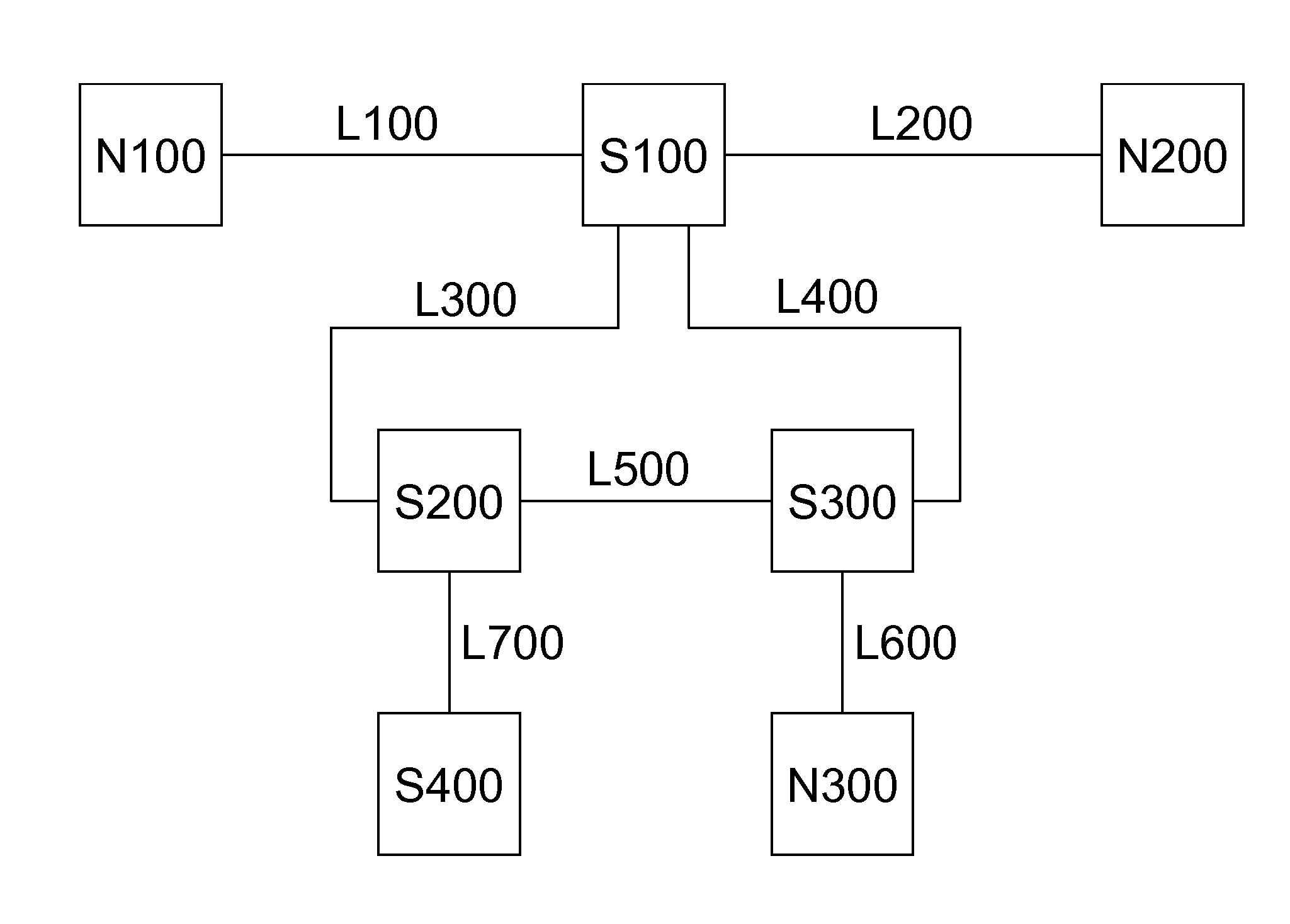
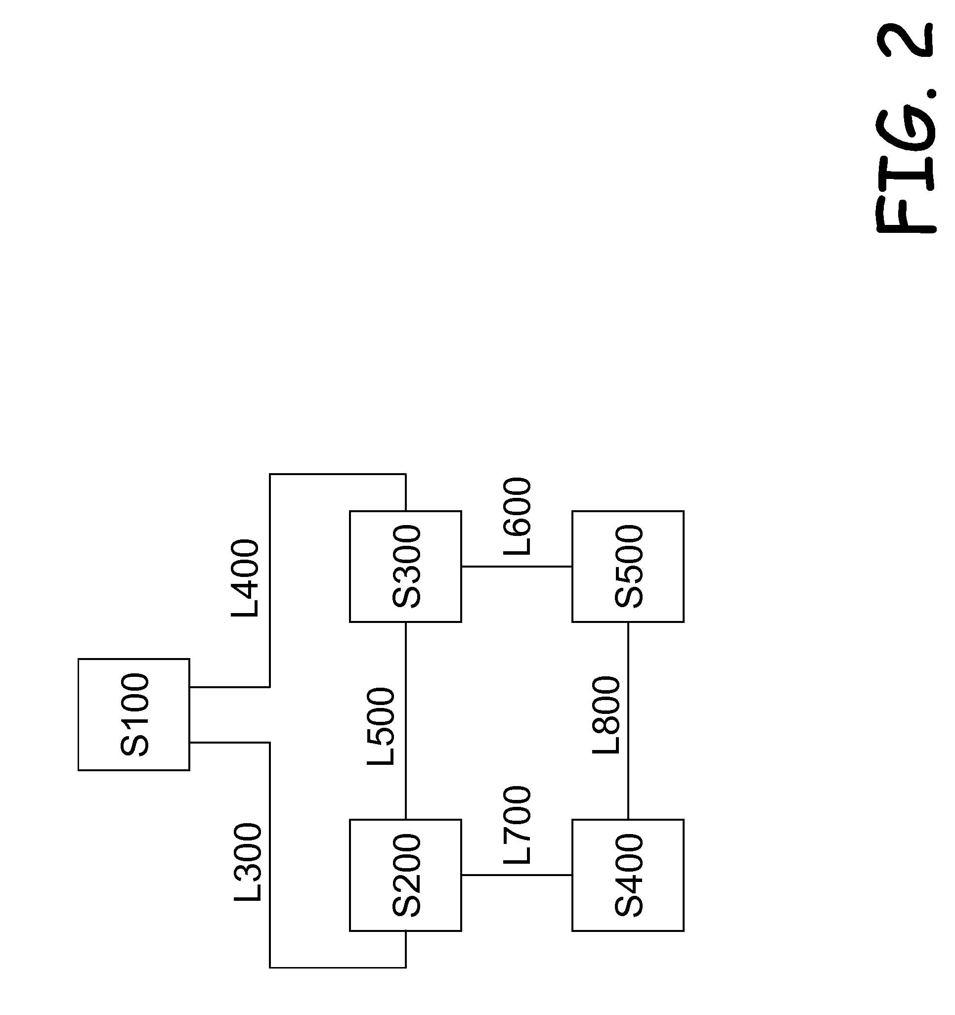
[0025]Turning now to the figures in which like numerals represent like elements throughout the several views, exemplary embodiments of the present invention are described. For convenience, only some elements of the same group may be labeled with numerals. The purpose of the drawings is to describe exemplary embodiments and not for production. Therefore features shown in the figures are chosen for convenience and clarity of presentation only.

[0026]In general, Ethernet switching devices such as Ethernet bridges as described in the art and as defined by standards such as IEEE Std 802.1D-2004, forward Ethernet frames based on destination addresses appearing on these frames. They may employ two modes of forwarding: forwarding to the destination through a single egress interface or forwarding to the destination through multiple interfaces excluding the one on which the frame has arrived, possibly limited to a subset of such interfaces as dictated by security or network partitioning direct...


PUM


Abstract

Disclosed herein are methods and systems for forwarding Ethernet frames over a redundant network with its links enabled utilizing shortest paths between nodes. Network nodes suppress traffic from traveling in loops by identifying and dropping recurring frames within a given (typically short) timeframe based on a set of increasingly significant tests enabling the identification of such frames using very low memory resources. In addition, correct node location learning is enabled by ignoring or dropping frames that contradict prior learning within a given (typically short) timeframe. This is achieved by identifying frames arriving from a single source on more than one ingress interface within a given (typically short) timeframe. Within this timeframe, only the frames arriving from such a source on the first interface the source is identified on are used for node location learning. This interface is hence treated as the only interface the source has been identified on for the purpose of the packet forwarding algorithm.

Description

CROSS-REFERENCE TO RELATED APPLICATIONS[0001]This application is a non-provisional application filed pursuant to 35 U.S.C. 1.53(b) and claims the benefit of the filing date of the United States provisional application for patent that was filed on Dec. 1, 2006, assigned Ser. No. 60 / 868,098 and bearing the title of “A Method and System for Forwarding Ethernet Frames over Redundant Networks with All Links Enabled”, which application is hereby incorporated by reference.FIELD OF THE INVENTION[0002]The present disclosure relates to redundant network configurations, and in particular, methods and systems for enabling switching systems to cope with frames looping in the network.BACKGROUND[0003]Packet-switched networks have become common for transferring many types of data among network nodes. In a packet-switched network, nodes share a communications channel via a virtual circuit, or non-dedicated connection through a shared medium that gives the high-level user the appearance of a dedicate...

Claims


Application Information

Patent Timeline
Patent Type & Authority Applications(United States)
IPC IPC(8): G08C15/00
CPCH04L45/00H04L45/18H04L49/555H04L49/351H04L47/32
Inventor KAEMPFER, GIDEON
Owner KAEMPFER GIDEON
Why Eureka
Try Eureka