
Receiver processing system

a processing system and receiver technology, applied in the direction of transmission, electrical equipment, etc., can solve the problems of insufficient, insufficient use of receiver hardware, and inability to meet the needs of the receiver,

Inactive Publication Date: 2008-06-05
KK TOSHIBA
View PDF11 Cites 1 Cited by
  • Summary
  • Abstract
  • Description
  • Claims
  • Application Information

AI Technical Summary

Benefits of technology

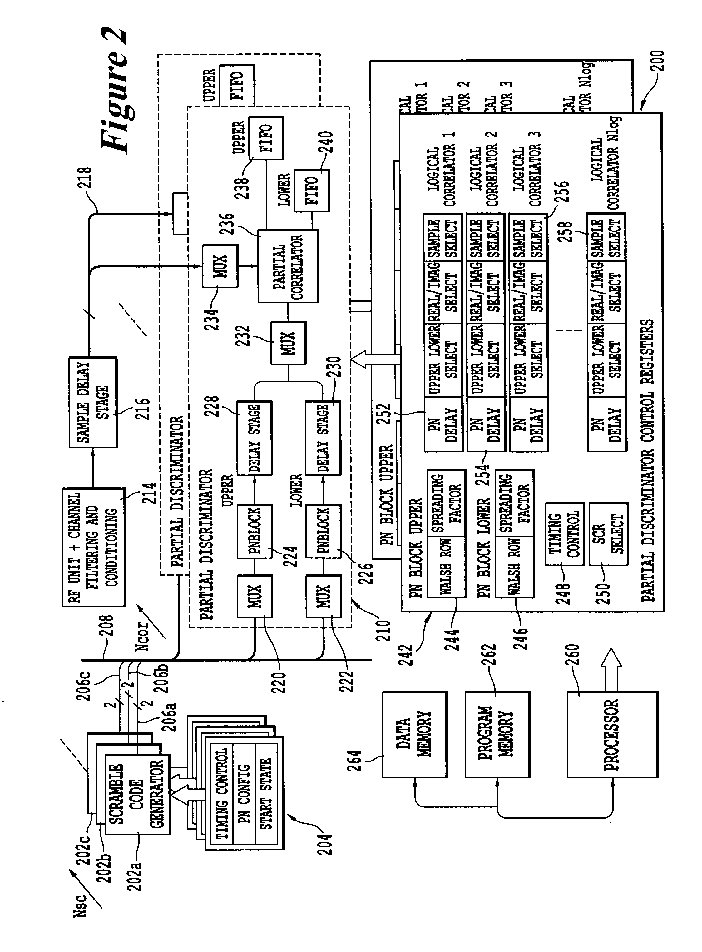
[0012]By providing two (or more) programmable spreading sequence generators which can be selectively coupled to the correlator module the correlator can be programmed to perform two or more separate casks by reallocation of the correlator module resource. The configuration also allows the correlator to be time multiplexed either to perform partial correlation calculations for a single result, such as real and imaginary correlations, or to perform separate correlation calculations to identify separate signals or signal components. The correlator can thus be used to support multiple wireless systems and / or multiple algorithms and adaptive algorithms. It also allows a manufacturer to modify a receiver design after the hardware has been embodied in silicon, and can therefore provide a software-defined radio. For example if the correlator is incorporated into a rake receiver the receiver can be arranged to vary the number of rake fingers according to the goodness of channel reception. A further advantage provided by the correlator is the scalability of its architecture. The components of the correlator may be implemented in either hardware or software or both.

Problems solved by technology

Theoretically this allows up to 64 simultaneous users of a given portion of spectrum but this is not necessarily sufficient, particularly because of the possibility of interference between users in different cells of the mobile phone network.
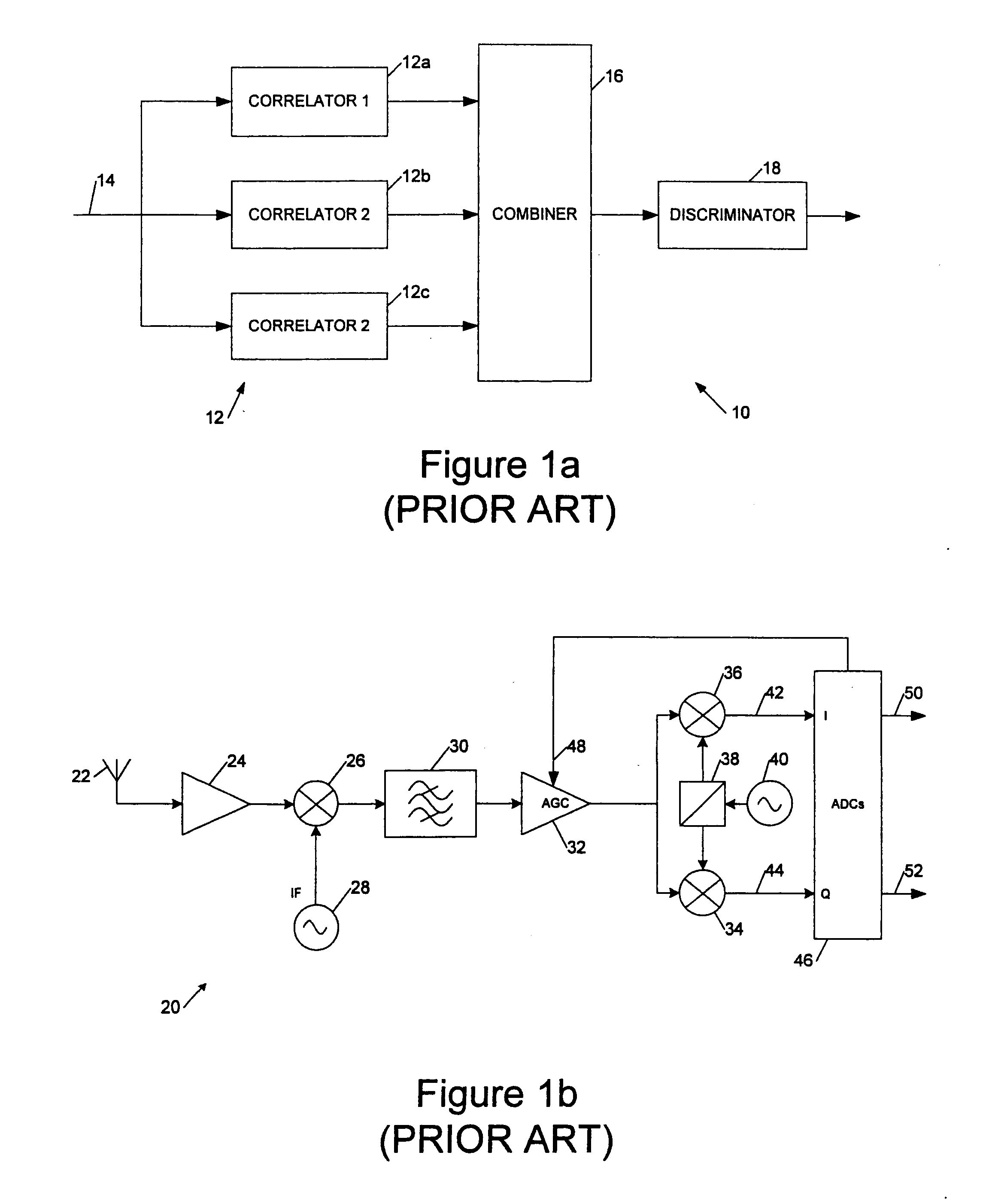
This has a number of disadvantages, in the main arising because such a fixed design will generally only be suitable for use with one particular wireless system configuration.
Even then it may make inefficient use of the receiver hardware as some functions, such as tracking correlators, can be redundant under some operational conditions.
Were the conventional approach to rake receiver design to be adopted the overall complexity would be very great as the system would need to be able to accommodate the extremes of the requirement specification, such as a large number of multirate channels in good channel conditions and low data rates in very bad channel conditions.

Method used


Image

  • Receiver processing system
  • Receiver processing system
  • Receiver processing system

Examples


Embodiment Construction

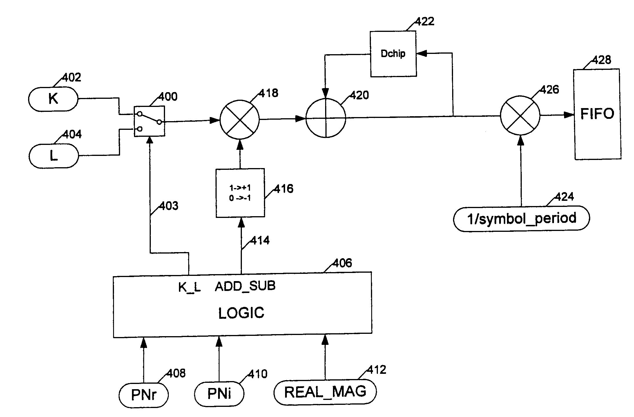
[0029]A rake receiver according to an embodiment of the present invention comprises one or more scramble code generators, one or more PN (pseudonoise) blocks, one or more partial complex correlators, one or more combiner modules, and a single discriminator allocation and configuration module. The receiver also includes a processor coupled to programme and data memory for setting up and controlling the receiver.

[0030]Each scramble code generator is capable of producing a complex (i.e. real and imaginary) binary PN sequence. The controlling processor can configure the precise timing and value of this sequence dynamically. Each PN block can select one of the scramble code generators as its input. The PN block also generates a binary spreading sequence derived from a row in a Walsh matrix. The (real) spreading sequence and the complex scramble code sequence are then combined to form a complex output sequence, which is here referred to as a combined PN sequence. The method of combining t...


PUM


Abstract

A spread spectrum receiver architecture comprising: a spread spectrum signal sampler; a sample delay stage, coupled to the spread spectrum sampler, to provide a set of spread spectrum samples having a plurality of different delays on a delayed sample bus; a plurality of scramble code generators to provide a plurality of scramble codes on a scramble code bus; and a plurality of correlators, each comprising a correlator module coupled to the delayed sample bus and comprising at least one spreading code generator coupled to the scramble code bus, and each said correlator having at least one correlation output.

Description

FIELD OF THE INVENTION[0001]This invention relates to spread spectrum receivers, in particular rake receivers. It has applications in 3G mobile phone systems.BACKGROUND TO THE INVENTION[0002]Third generation mobile phone networks use CDMA (Code Division Multiple Access) spread spectrum signals for communicating across the radio interface between a mobile station and a base station. A 3G network is known as a UMTS (Universal Mobile Telecommunications System) network and UMTS is the subject of standards produced by the Third Generation Partnership Project (3GPP, 3GPP2). Technical specifications for 3GPP and 3PGG2 can be found at www.3gpp.org. and are hereby incorporated by reference.[0003]In a CDMA spread spectrum communication system a baseband signal is spread by mixing it with a pseudorandom spreading sequence of a much higher bit rate (referred to as the chip rate) before modulating the rf carrier. At the receiver the baseband signal is recovered by feeding the received signal and...

Claims


Application Information

Patent Timeline
Patent Type & Authority Applications(United States)
IPC IPC(8): H04B1/707H04B1/709H04B1/7113H04B1/7115H04B1/7117
CPCH04B1/709H04B1/7113H04B1/7115H04B2201/70711H04B2201/70707H04B2201/7071H04B1/7117
Inventor DOLWIN, ANTHONY CRAIG
Owner KK TOSHIBA
Learn More