Center of gravity sensing and adjusting load bar, program product, and related methods

a technology of center of gravity and load bar, applied in the field of load control, can solve the problems of increasing floor space requirements, consuming one hour or more to adjust the load bar, and consuming three hours or more to perform the move, so as to achieve safe lifting and stabilization

Active Publication Date: 2008-06-05
LOCKHEED MARTIN CORP
View PDF11 Cites 32 Cited by
  • Summary
  • Abstract
  • Description
  • Claims
  • Application Information

AI Technical Summary

Benefits of technology

[0010]In view of the foregoing, embodiments of the present invention advantageously provide an adjusting load bar system, apparatus, program product, and method for safely lifting and stabilizing high-value components or modules such as aircraft modules, that includes an adjusting load bar control system which, for example, utilizes electronic tilt sensors, compact industrial computers, direct current pulse width modulation motor drives, absolute position feedback encoders, direct current motors, linear screw drive actuators and a custom software package controlled through a mobile control cart having touch screen with a graphical user interface.

Problems solved by technology

Finding the center of gravity at each staging area can be extremely time-consuming.
Moves of various components using such conventional load bars, for example, however, could result in the consumption of one hour or more to adjust the load bar and three hours or more to perform the move.
The requirement for eighteen load bars, in turn, besides being undesirable due to equipment costs, significantly increases floor space requirements.
Automated systems designed for centering a lifting device and used for extracting low value components such as, for example, mobile homes, etc., were examined, but found to have undesirable limitations.
Such device, extracted using a single hook assembly, however, required significant deviation in the leveling of the component to be lifted prior to attempting to properly center itself above the component to be lifted.
Further, such device did not provide either redundant control systems or a multi-level safety control system, or even adequate automated visual means of indicating an out of tolerance condition.

Method used


Image

  • Center of gravity sensing and adjusting load bar, program product, and related methods
  • Center of gravity sensing and adjusting load bar, program product, and related methods
  • Center of gravity sensing and adjusting load bar, program product, and related methods

Examples


Embodiment Construction

[0034]The present invention will now be described more fully hereinafter with reference to the accompanying drawings, which illustrate embodiments of the invention. This invention may, however, be embodied in many different forms and should not be construed as limited to the illustrated embodiments set forth herein. Rather, these embodiments are provided so that this disclosure will be thorough and complete, and will fully convey the scope of the invention to those skilled in the art.

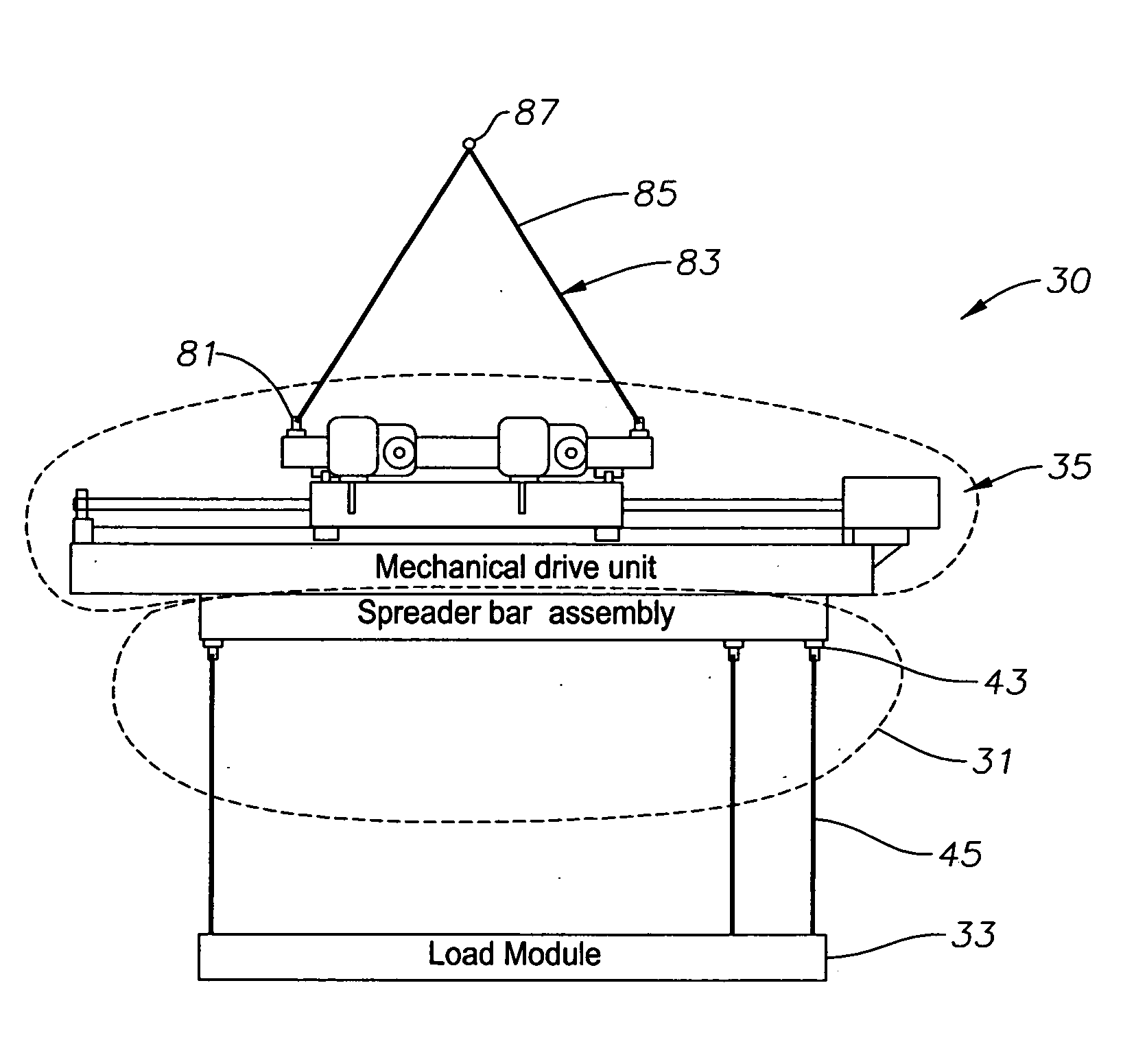
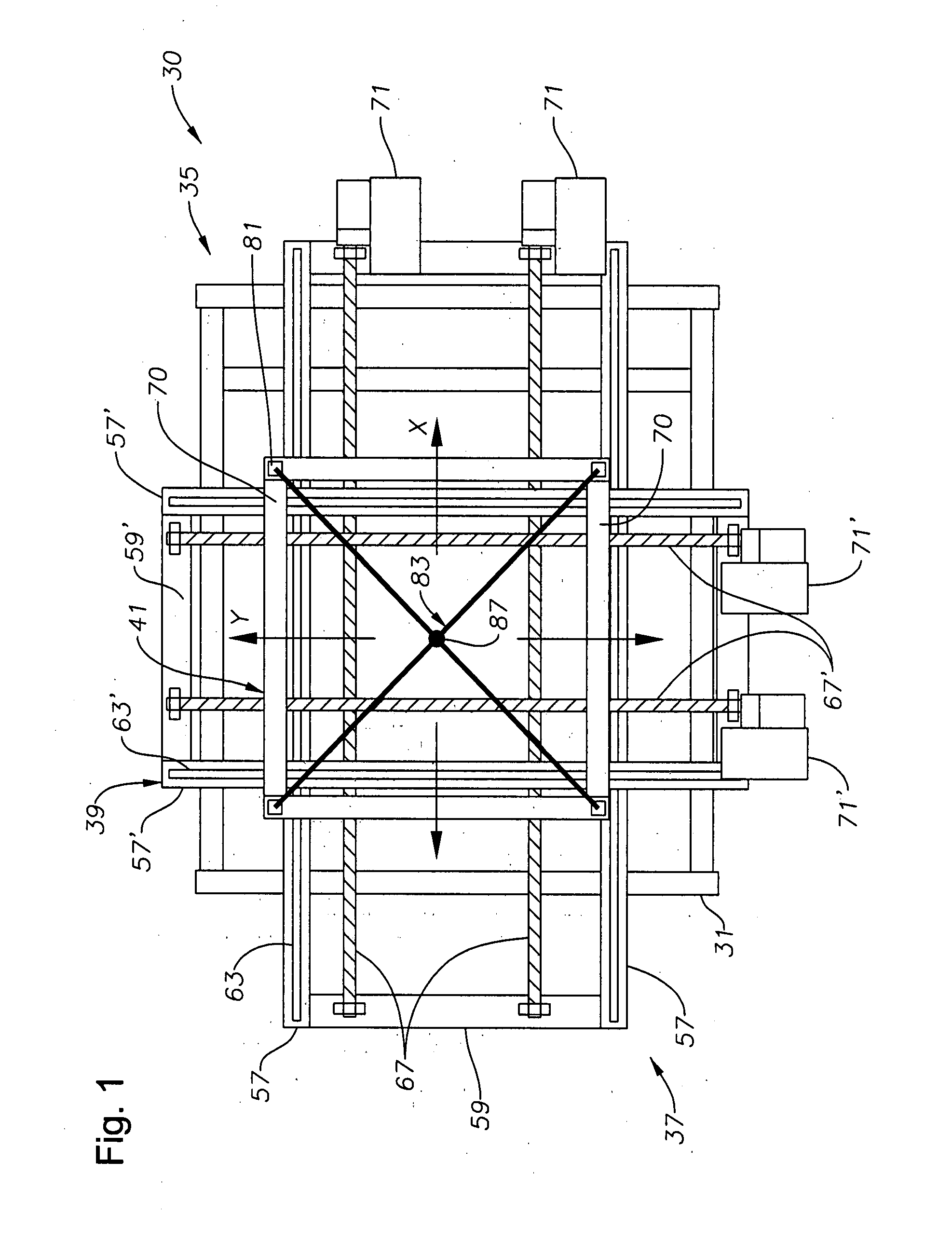
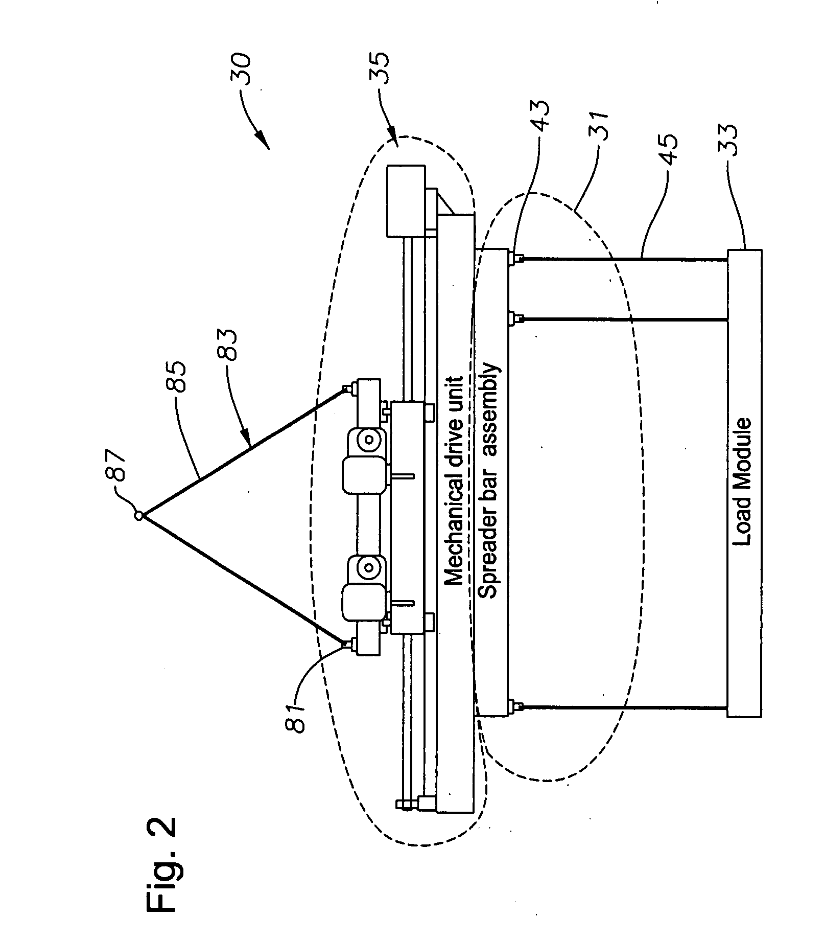
[0035]In the Aerospace and other vehicle or component production industries, for example, numerous assembly station moves with different component weights and center of gravity (CG) configurations exist. Embodiments of the present invention provide an adjusting load bar apparatus for lifting and stabilizing high-value components or modules, e.g., aircraft modules, or other loads under an overhead crane or other overhead carrier device. Beneficially, embodiments of the apparatus can be used within, for e...


PUM


Abstract

An apparatus, program product, and related methods for gravity stabilizing a suspended load are provided. The apparatus includes an center of gravity stabilized automated adjusting load bar in communication with a mobile cart which allows an operator to enable automated stabilization of a load. The adjusting load bar includes redundant first and second control and drive systems. A third control system can both monitor sensed data and the movement commands of first and second control systems, and can monitor the resulting physical movements. If a movement command and the resulting movement does not match or if there is an out of tolerance mismatch between movement commands of the first and the second control systems, the third control system can automatically detect this condition and shift into an emergency stop condition.

Description

RELATED APPLICATIONS[0001]This patent application claims the benefit of and priority to U.S. Provisional App. No. 60 / 872,259, filed on Dec. 1, 2006, incorporated by reference herein in its entirety.BACKGROUND OF THE INVENTION[0002]1. Field of the Invention[0003]The present invention relates generally to the field of load control, and particularly to the controlling and safely stabilizing a load being suspended under an overhead carrier. More specifically, the present invention relates to a system, apparatus, program product, and related methods for gravity stabilizing a suspended load.[0004]2. Description of the Related Art[0005]Modules or portions of the aircraft are assembled at various stages along an assembly floor. When the work in any particular stage is completed, an overhead crane extracts the module and delivers it to the next stage. Because components are being added at each staging area, the center of gravity of the module changes from stage to stage. The module needs to ...

Claims


Application Information

Patent Timeline
Patent Type & Authority Applications(United States)
IPC IPC(8): B66C1/00G06F7/00
CPCB66C13/04B66F9/18B66C1/10B66C13/08
Inventor FRIZ, DANIEL C.BATES, MARK R.
Owner LOCKHEED MARTIN CORP
Why Eureka
Try Eureka