RMC-defined tip blowing slots for turbine blades

a turbine blade and blowing slot technology, applied in the direction of machines/engines, waterborne vessels, foundry moulds, etc., can solve the problems of oxidation and erosion of the tip of the rotor blade, difficult to determine the external thermal boundary conditions near the tip, and difficult to design a cooling configuration. , to achieve the effect of more reliable casting process and efficient use of cooling air

Inactive Publication Date: 2008-06-05
UNITED TECH CORP
View PDF9 Cites 48 Cited by
  • Summary
  • Abstract
  • Description
  • Claims
  • Application Information

AI Technical Summary

Benefits of technology

[0007]In accordance with the present invention, there is provided a new tip cooling design that utilizes refractory metal core (RMC) technology in order to create a tip cooling scheme for a turbine engine component that is capable of more efficient use of cooling air and a more reliable casting process.

Problems solved by technology

One of the typical failure modes for high pressure turbine (HPT) rotor airfoils (blades) is tip distress via oxidation and erosion.
It is particularly challenging to design a cooling configuration for a tip region for a variety of reasons.
First, it is very difficult to determine the external thermal boundary conditions near the tip due to the highly-three dimensional nature of the gaspath flow.
Also, the tip region of a turbine blade is typically the thinnest portion of the airfoil, which makes it more difficult to package the desired cooling features.
Furthermore, the tip region of a turbine blade is typically difficult to accurately produce with investment casting processes because the internal ceramic core is thin and weak near the tip.
However, it is desirable to have the tip print-out holes be smaller so that they do not flow an excessive amount of cooling air in the finished part, which results in inefficiency in the cooling design and, therefore, the turbine performance.

Method used


Image

  • RMC-defined tip blowing slots for turbine blades
  • RMC-defined tip blowing slots for turbine blades
  • RMC-defined tip blowing slots for turbine blades

Examples


Embodiment Construction

)

[0018]As noted before, a new tip cooling design for a turbine blade is proposed here that utilizes refractory metal core technology in order to help create a tip cooling scheme that is capable of more efficient use of cooling air and a more reliable casting process.

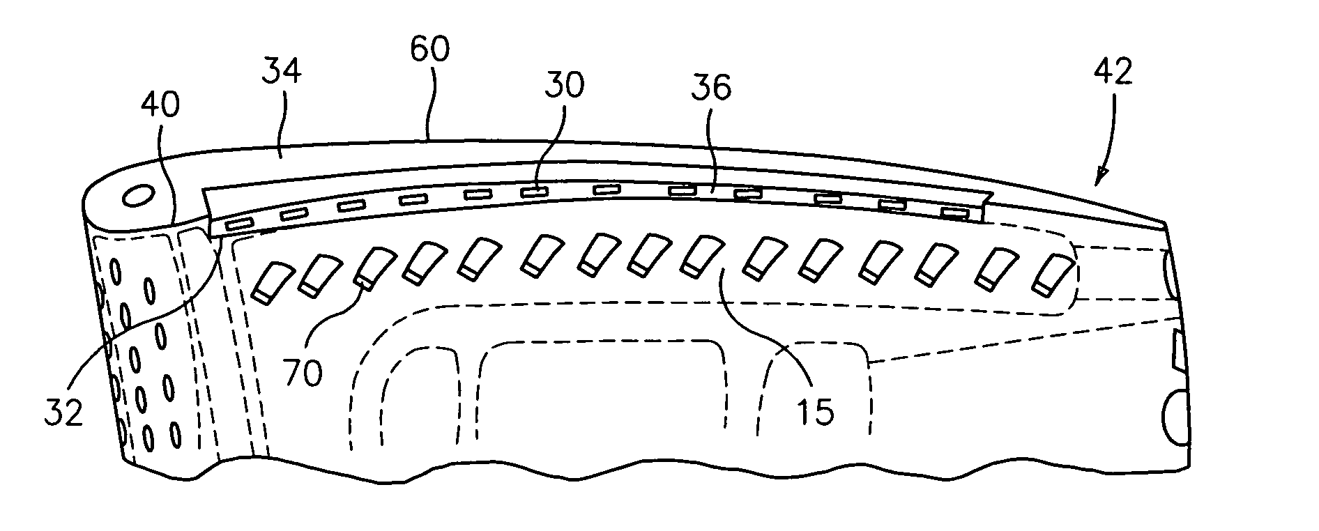
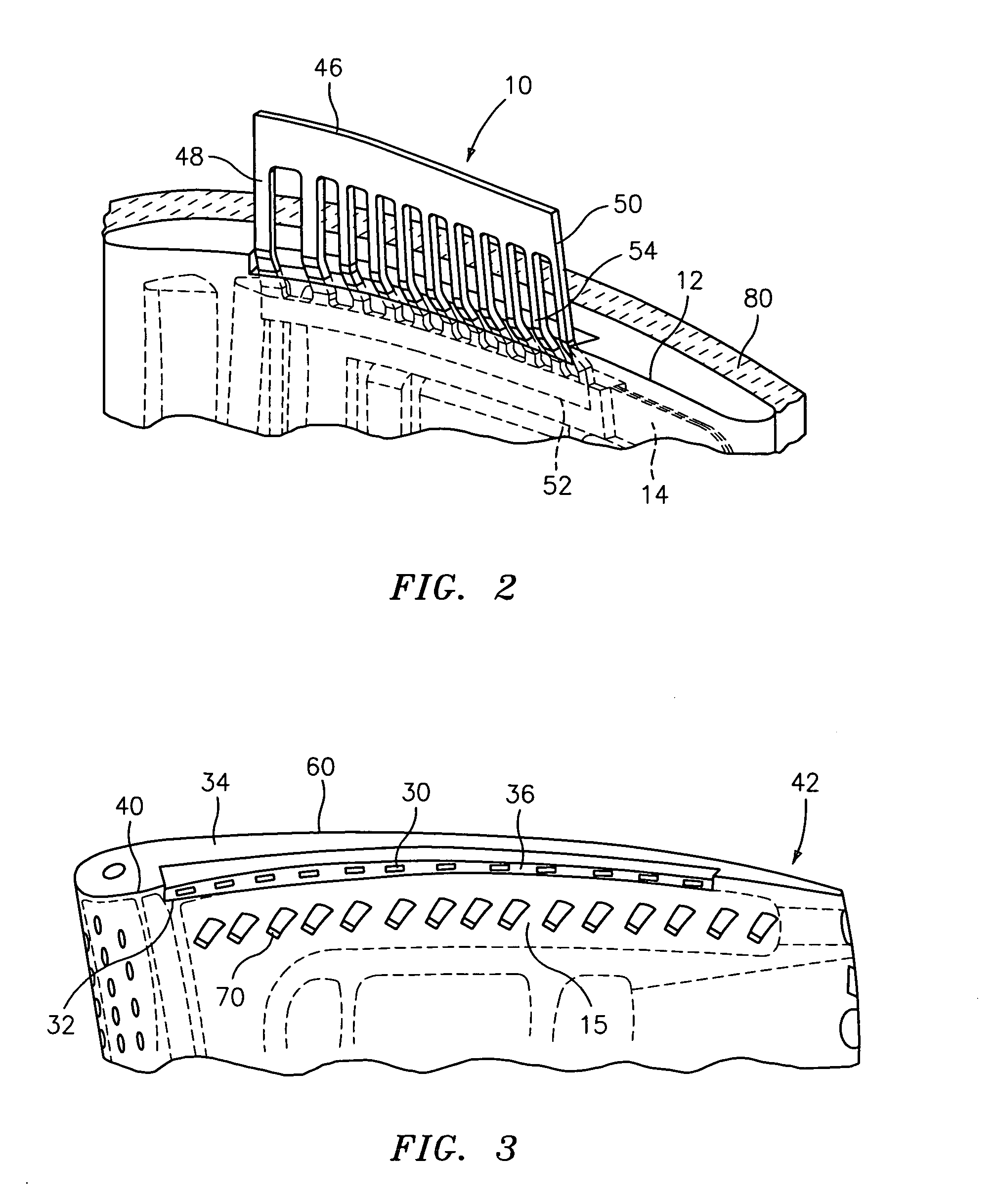
[0019]Referring now to FIG. 2, a relatively thin, approximately 0.015″, refractory metal core element 10 is used to stabilize a tip region 12 of a ceramic core 14 during the casting process. The ceramic core 14 is positioned within a mold 80, only a portion of which has been shown. The ceramic core 14 may have the configuration of a laterally oriented passageway 15 to be formed in the airfoil tip region 34. The refractory metal core element 10 is printed out of the airfoil tip region 34 during casting and is located laterally of the ceramic core 14. Preferably, the refractory metal core element 10 is positioned adjacent a side of the mold which forms the pressure side 40 of the airfoil portion 42. The refractory metal co...


PUM

PropertyMeasurementUnit
refractoryaaaaaaaaaa
pressureaaaaaaaaaa
heataaaaaaaaaa

Abstract

A process for forming an airfoil portion of a turbine engine component, such as a turbine blade, is described. The process comprises the steps of placing a ceramic core having a configuration of a passageway to be formed in the airfoil portion within a mold, attaching a refractory metal core element to the ceramic core to stabilize a tip region of the ceramic core, and casting the airfoil portion.

Description

BACKGROUND[0001](1) Field of the Invention[0002]The present invention relates to a process for forming a turbine engine component, such as a turbine blade, having a plurality of as-cast blowing slots in a tip region using a refractory core element.[0003](2) Prior Art[0004]One of the typical failure modes for high pressure turbine (HPT) rotor airfoils (blades) is tip distress via oxidation and erosion. It is particularly challenging to design a cooling configuration for a tip region for a variety of reasons. First, it is very difficult to determine the external thermal boundary conditions near the tip due to the highly-three dimensional nature of the gaspath flow. Also, the tip region of a turbine blade is typically the thinnest portion of the airfoil, which makes it more difficult to package the desired cooling features. Furthermore, the tip region of a turbine blade is typically difficult to accurately produce with investment casting processes because the internal ceramic core is t...

Claims


Application Information

Patent Timeline
Patent Type & Authority Applications(United States)
IPC IPC(8): F01D5/18F01D25/12B22D15/00B22D19/00B21D53/78
CPCB22C9/04B22C9/103F01D5/147Y10T29/49337F05D2230/211F05D2300/13F01D5/187
Inventor ALBERT, JASON EDWARDCUNHA, FRANCISCO J.BEATTIE, JEFFREY S.
Owner UNITED TECH CORP
Why Eureka
Try Eureka