Artificial Spinal Disc

a technology of artificial discs and discs, applied in the field of disc disease and spinal deformities with artificial disc replacement, can solve the problems of insufficient adjustment of insertion angle, inability to correct an underlying deformity of the spine, and inability to use wedge-shaped end plates. to prevent a hard stop

Active Publication Date: 2008-06-05
SYNERGY SPINE SOLUTIONS INC
View PDF99 Cites 203 Cited by
  • Summary
  • Abstract
  • Description
  • Claims
  • Application Information

AI Technical Summary

Benefits of technology

[0019]An alternate method of achieving lordotic correction is by changing the nucleus or inner core. The biggest advantage of this approach is that the nucleus or core can be more easily interchanged or revised. Intra-operatively, instruments can be used to gage the need for and amount of correction and the appropriate nucleus can be inserted. By designing the correction into the nucleus, the surgeon is provided with flexibility and ease of insertion, and the ability for revision at a later date, which the other methods do not provide.
[0041]The end plates can be provided with features that act as stops outside of the desired range of motion, which allow for anatomically-derived gradual stopping. This result can be achieved by forming one or more camming surfaces in or on one of the end plates and providing a co-operating member on the other end plate for engaging the camming surface. The camming surface has a gradual curve on its inner surface. During relative movement between the end plates, the camming surface is engaged by the cooperating member, which results in an axial distraction of the end plates and provides a soft tissue assist to prevent a hard stop. Alternatively for rotational movement, cooperating camming surfaces can be provided so that distraction will occur when one end plate rotates relative to the other one.

Problems solved by technology

Unfortunately, by changing only the angle of insertion, one cannot correct an underlying deformity of the spine.
Simply changing the angle of insertion is not adequate to compensate for a device that does not have sufficient off-center load bearing support or structure to maintain the correction of the deformity.
However, wedge-shaped end plates are not routinely available at the present time for cervical disc replacement systems.
The disadvantage, however, is that this strategy is not forgiving if an error is made with either an overly corrected end plate or an end plate that is not corrected enough.
The revision of the end plate can be difficult at the time of surgery and may even preclude the disc space from receiving a disc replacement.
As most systems have a coating on the end plates that promote bony ingrowth, revision at a later date may be extremely difficult or even impossible.

Method used


Image

  • Artificial Spinal Disc
  • Artificial Spinal Disc
  • Artificial Spinal Disc

Examples


Embodiment Construction

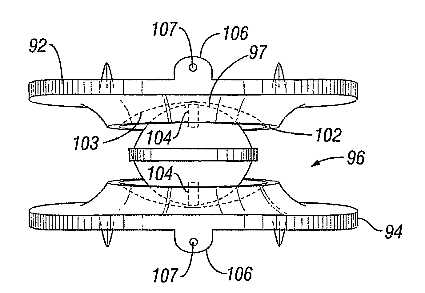
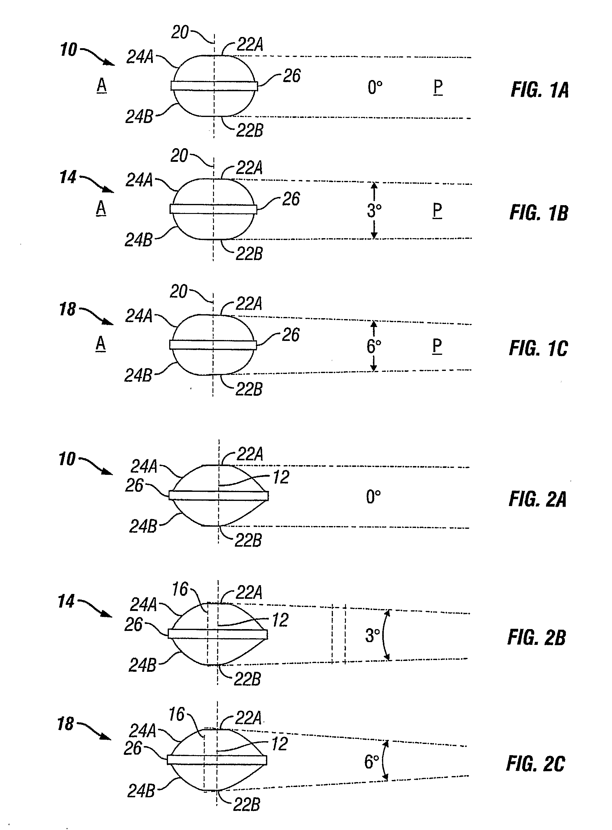
[0077]In its proper, healthy alignment, the spine follows natural curves, which promote proper sagittal and coronal balance (flexibility) and allow for balanced load sharing between the vertebrae. These curves include the cervical, thoracic, lumbar and sacral regions of the spine. Naturally, in order to accommodate a curve, there must be some variation in the angle of articulation between the functional spinal units and the height of an intradiscal space. The cervical and lumbar regions are naturally lordotic, or curved convexly in the anterior direction. At different segments along the spine, there are typically different heights for the vertebral bodies and the intradiscal space. In addition, the intradiscal space and vertebral body height may be different for different people.

[0078]Each intradiscal space has anterior and posterior regions. An artificial disc in the cervical, thoracic and lumbar regions that maintain the same height from the anterior to the posterior may promote a...


PUM

PropertyMeasurementUnit
angleaaaaaaaaaa
angleaaaaaaaaaa
shapeaaaaaaaaaa

Abstract

An artificial disc prosthesis is provided. The prosthesis of the present invention enables spinal segment alignment by having a variable height across its surface. The variable height is achieved by an asymmetric artificial nucleus or by at least one variable height end plate.

Description

TECHNICAL FIELD[0001]The present invention relates to methods and devices for the treatment of disc disease and spinal deformities with an artificial disc replacement.BACKGROUND OF THE INVENTION[0002]Spinal arthroplasty is an emerging field that offers the promise of restoring and / or maintaining normal spinal motion. The goal of spinal arthroplasty is to reduce or eliminate adjacent segment disease (ASD) by maintaining the normal spinal biomechanics at the operative level. To accomplish this, an artificial cervical prosthesis must duplicate as closely as possible the natural spinal biomechanics, including maintaining the axial height of the disc as well as applying angular adjustment throughout the full range of motion of the natural spine.[0003]The spine plays an integral role in neural protection, load bearing and motion. The vertebral column provides a strong, yet mobile central axis for the skeleton and is composed of twenty-four vertebral bodies with seventy-five stable articul...

Claims


Application Information

Patent Timeline
Patent Type & Authority Applications(United States)
IPC IPC(8): A61F2/44
CPCA61F2/4425A61F2310/00796A61F2/4657A61F2/4684A61F2002/302A61F2002/30232A61F2002/30242A61F2002/30354A61F2002/30364A61F2002/30369A61F2002/30383A61F2002/3039A61F2002/30397A61F2002/30426A61F2002/305A61F2002/30535A61F2002/30538A61F2002/30563A61F2002/30578A61F2002/30604A61F2002/30616A61F2002/3065A61F2002/30654A61F2002/30662A61F2002/30663A61F2002/30685A61F2002/3069A61F2002/30841A61F2002/30884A61F2002/30892A61F2002/30904A61F2002/443A61F2220/0025A61F2220/0033A61F2230/0065A61F2230/0069A61F2230/0071A61F2250/0006A61F2250/0058A61F2310/00017A61F2310/00023A61F2310/00029A61F2310/00179A61F2310/00407A61F2/4611A61F2/44
Inventor DUGGAL, NEILRAYMOND, LOUISEBAKER, DANIEL R.CONTA, ROBERTTHALER, CARLY A.STINSON, DAVID T.
Owner SYNERGY SPINE SOLUTIONS INC
Why Eureka
Try Eureka