Self powered heat transfer fan

a self-powered, fan technology, applied in the direction of heating types, applications, lighting and heating apparatus, etc., can solve the problems of insufficient and reliable use, thermoelectric modules simply overheating and being destroyed, and the tellurex corporation demonstration model has no practical and reliable utility as a warm air circulating fan, and achieves satisfactory air circulation

Active Publication Date: 2008-06-12
REID RANDALL H
View PDF14 Cites 15 Cited by
  • Summary
  • Abstract
  • Description
  • Claims
  • Application Information

AI Technical Summary

Benefits of technology

[0031]Hence, fans according to the invention, can provide satisfactory air circulation when the fan module is operative at a temperature gradient of the order of as low as 30° C.

Problems solved by technology

It is clear from this demonstration model that it could not be satisfactorily and reliably used to circulate heat from a hot surface, since sufficiently high temperatures of the hot surface sufficient to provide an effective air circulation effect would cause the thermoelectric module to simply overheat and be destroyed.
Thus, the Tellurex Corporation demonstration model has no practical and reliable utility as a warm air circulating fan if placed on a heated surface.
Further, U.S. Pat. No. 5,544,488 teaches that an air circulation fan powered only by a thermoelectric module cooled at the cooling surface of a cooling system, such as, for example, provided by ice / water or a refrigeration system can provide useful air circulation, notwithstanding the extremely low efficiency of conversion of thermal energy to electrical energy inherent in the Seebeck Thermocouple Effect.

Method used


Image

  • Self powered heat transfer fan
  • Self powered heat transfer fan
  • Self powered heat transfer fan

Examples


Embodiment Construction

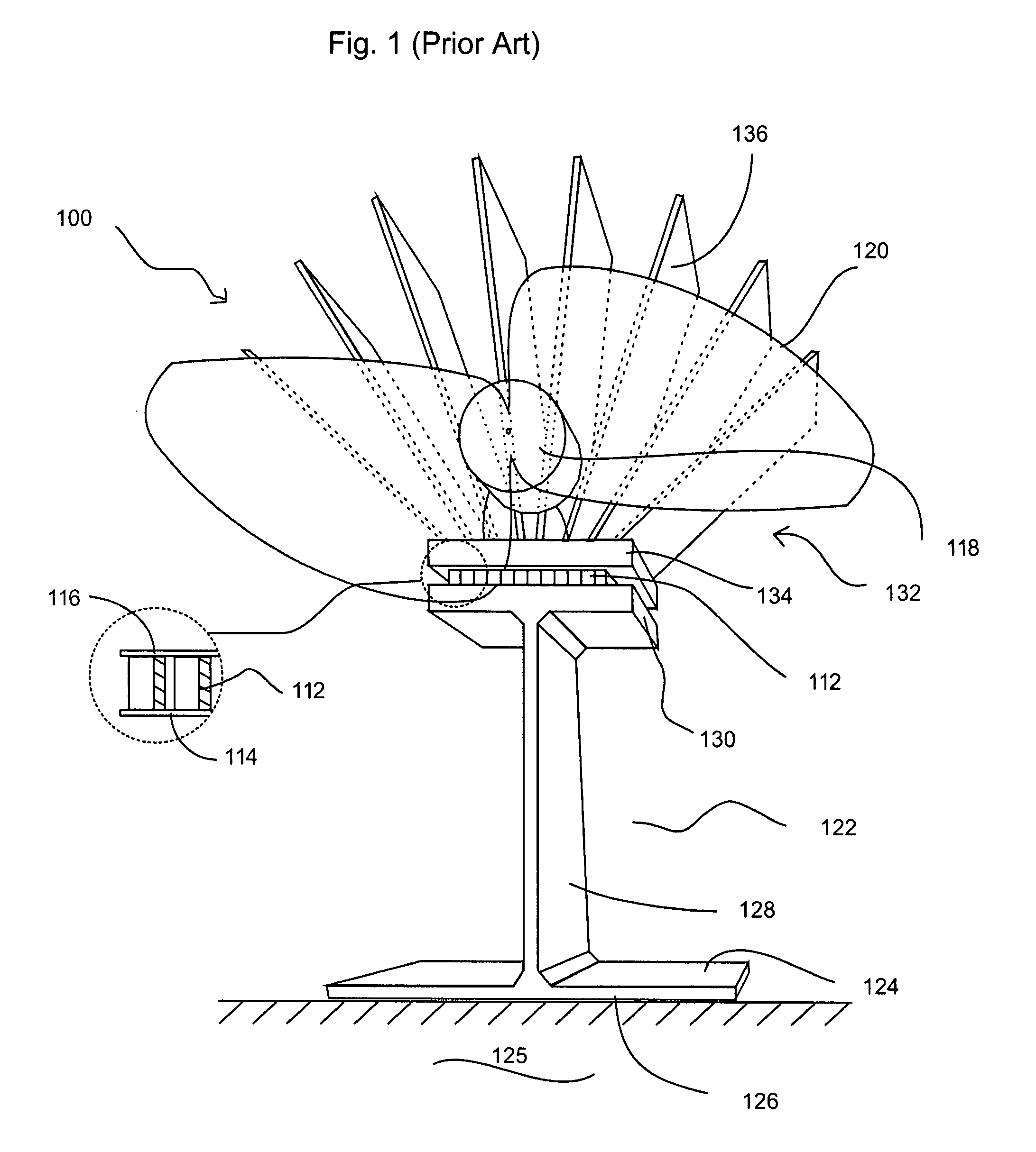
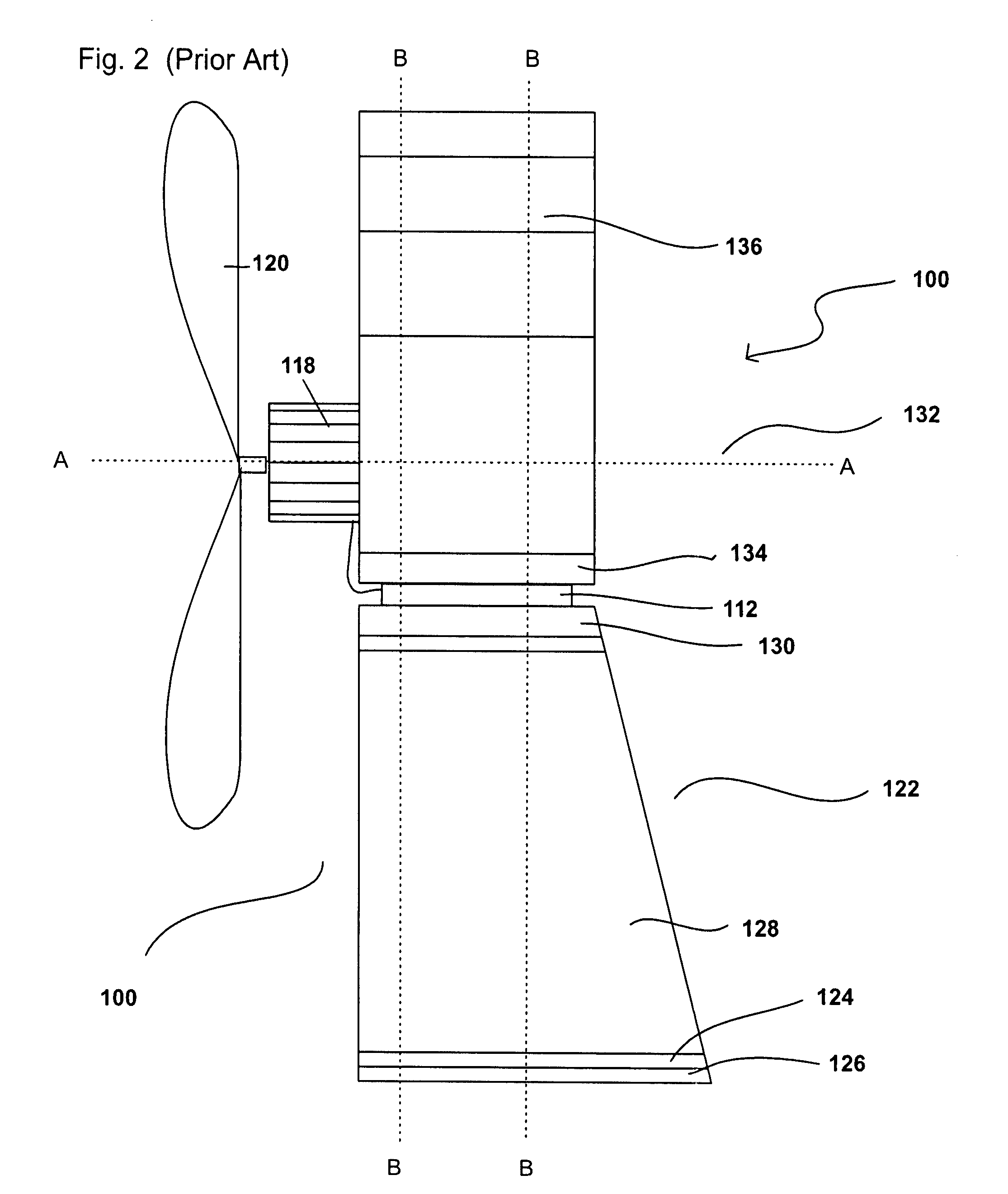
[0045]With reference to FIGS. 1 and 2, fan 100 of the prior art exemplified by U.S. Pat. No. 5,544,488 comprises a TE module 112 (cpl. 0-127-08L Melcor Frigichips, U.S.A.) comprised of an array of semiconductor couples (P and N pellets) connected electrically in series and thermally in parallel sandwiched between metallized ceramic substrates 114 and 116 according to the prior art. This module 112 can withstand temperatures only up to about 80.degree. C. Module 112 has an electrical connection with motor 118, which, drives fan blades 120, shown in outline only for clarity.

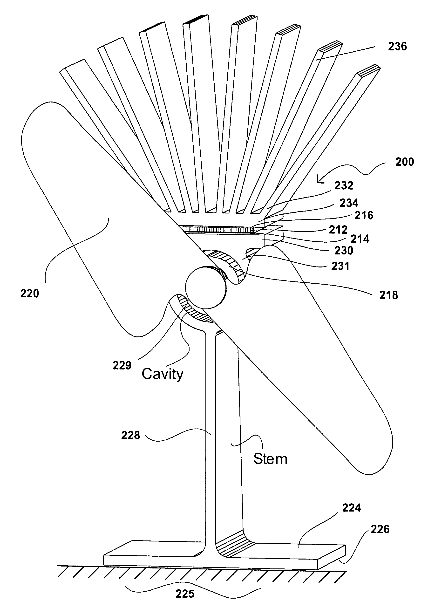
[0046]Fan 100 has a heat transfer member, shown generally as 122 having a rectangular-shaped base portion 124 having a lower surface 126 in operable contact with a heated surface of a stove or the like 125. Upstanding from rectangular base member 124 is an integrally formed vertically aligned planar heat transfer portion 128 upon which is an integrally formed heat transfer portion 130. Member 122 is, thus, constitu...


PUM


Abstract

A self-powered fan for circulating air for use in cooperation with a heat source, such as a wood stove, and having a first heat transfer member thermally and physically connected with the heat source. The fan blades operably create a first or warm air flow and a second or cooler air flow. The fan has a second heat transfer member with a thermocouple module structure located between the two heat transfer members. The first heat transfer member is of suitable material, size, mass and shape as to provide a suitable temperature gradient between the thermocouple structure and the heat source to operably allow of such sufficient heat transfer from the first heat transfer member to the thermocouple to generate sufficient power to effect rotation of the blades, but not to cause thermal damage to the thermocouple structure. The fan blades are constructed and arranged to cause a portion of the second air flow to be drawn past the first heat transfer member to effect a cooling heat transfer effect upon the first heat transfer member. The improvement is wherein the motor located on the first transfer member adjacent a side of the thermocouple structure remote from the second transfer member does not hinder the second air flow, and is suitably located as to not be operably thermally damaged by the first heat transfer member or the heat source.

Description

FIELD OF THE INVENTION[0001]This invention relates to heat transfer fans, particularly to such fans for use in conjunction with cooled or heated surfaces, and more particularly, with fossil-fuel burning stoves.BACKGROUND OF THE INVENTION[0002]Heating units such as wood and other fossil-fuel combustible material burning stoves, hot water radiators and the like disseminate heat into surrounding space by radiation and by convection of thermal air currents circulating around the unit. Warm air distribution from the unit may be enhanced by means of an air blower or fan suitably placed on or adjacent the unit. Presently, such air circulating fans are powered by electric battery or mains power supply.[0003]It is known through the so-called “Peltier Effect” that when a direct electric current is passed through a thermoelectric couple, heat will be absorbed at one end of the couple to cause cooling thereof, while heat is rejected at the other end of the couple to cause a rise in temperature....

Claims


Application Information

Patent Timeline
Patent Type & Authority Applications(United States)
IPC IPC(8): F04D25/02
CPCF04D25/04F04D29/582F24B7/025F24B7/00F04D29/601
Inventor REID, RANDALL H.
Owner REID RANDALL H
Why Eureka
Try Eureka