
Frame Saw

Inactive Publication Date: 2008-06-12
WINTERSTEIGER
View PDF17 Cites 5 Cited by
  • Summary
  • Abstract
  • Description
  • Claims
  • Application Information

AI Technical Summary

Benefits of technology

[0003]The invention is based on the object of arranging a frame saw of the kind mentioned above in such a way that a noticeable increase in the stroke frequency of the reciprocating saw frame can be achieved without needing to fear an overload of the guide means of the reciprocating saw frame. Moreover, it should be possible to carry out a change of the sash with a low amount of reconfiguration work.
[0006]In order to improve the cutting speed on the one hand and the cutting precision on the other hand, the guide means for the crossbeam and the basic frame can be arranged in the area of the stringer which is remoter from the slider-crank drive as recirculating ball bearing guides which enable a substantially play-free displacement guidance of the reciprocating saw frame, which also leads to an extension of the service life of the saw-blades.
[0007]The crossbeam which is held on the lateral guide rails and is connected to the slider-crank drive not only allows for favorable introduction of force into the sash, but also offers simple changing conditions for the reciprocating saw frame because it is not necessary to detach the drive connection between the crossbeam and the slider-crank drive for removing the sash. Favorable constructional conditions are obtained in this connection when the crossbeam is inserted into a receiving groove of the stringer closer to the slider-crank drive, because in this case the sash merely needs to be lifted from the receiving groove after the detachment of its connection with the guide means in the area of the sturdy beam remoter from the slider-crank drive. The play-free receiving of the crossbeam in the receiving groove of the stringer can advantageously be achieved in such a way that the receiving groove of the stringer comprises groove walls converging towards the base of the groove, on which rests the crossbeam with respectively inclined opposite surfaces as soon as the cross-beam is pulled against the base of the receiving groove with the help of fastening screws for example.

Problems solved by technology

Despite these constructional preconditions for a comparatively light design, the achievable stroke frequency remains limited.

Method used


Image

  • Frame Saw
  • Frame Saw
  • Frame Saw

Examples


Embodiment Construction

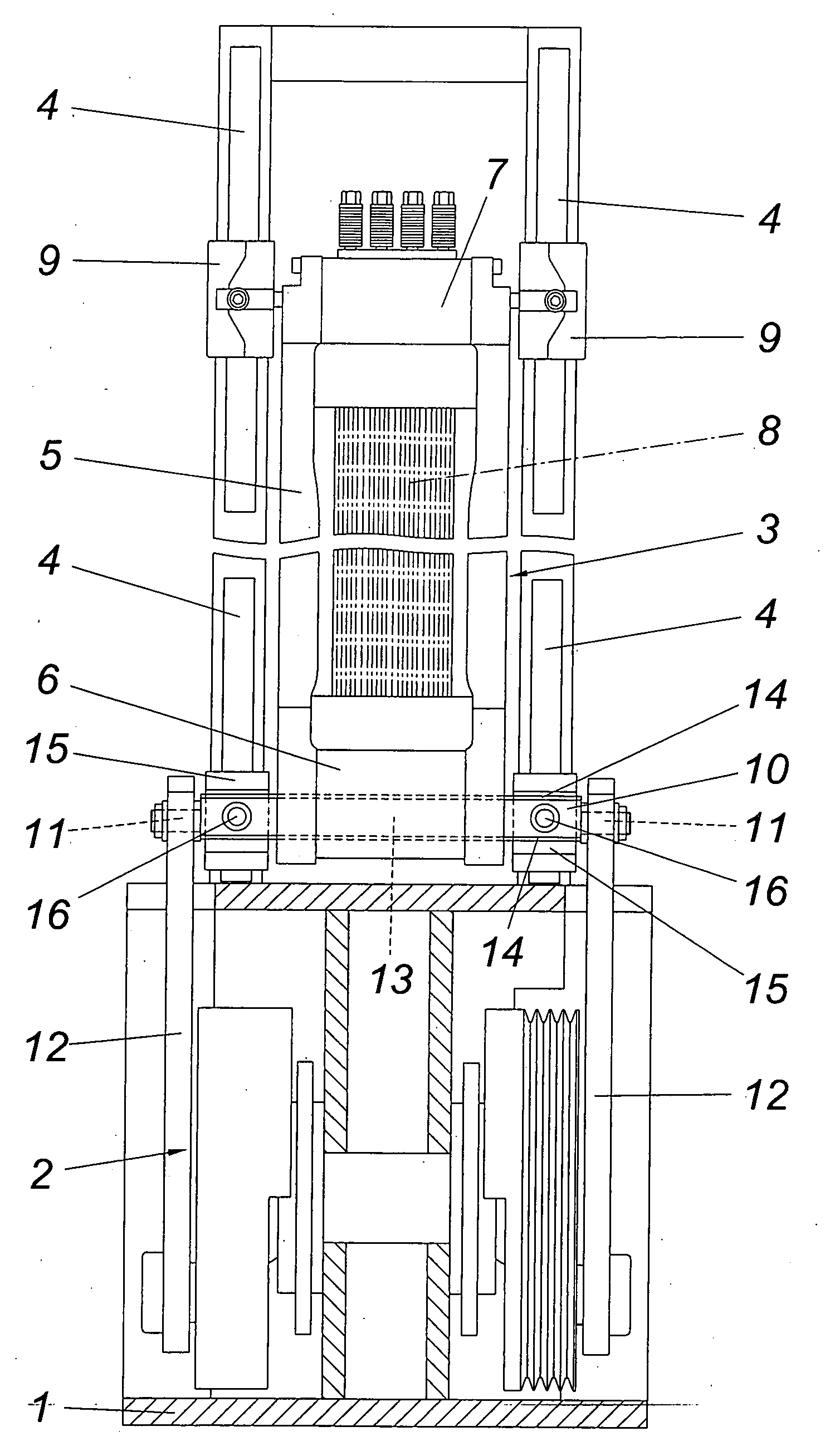
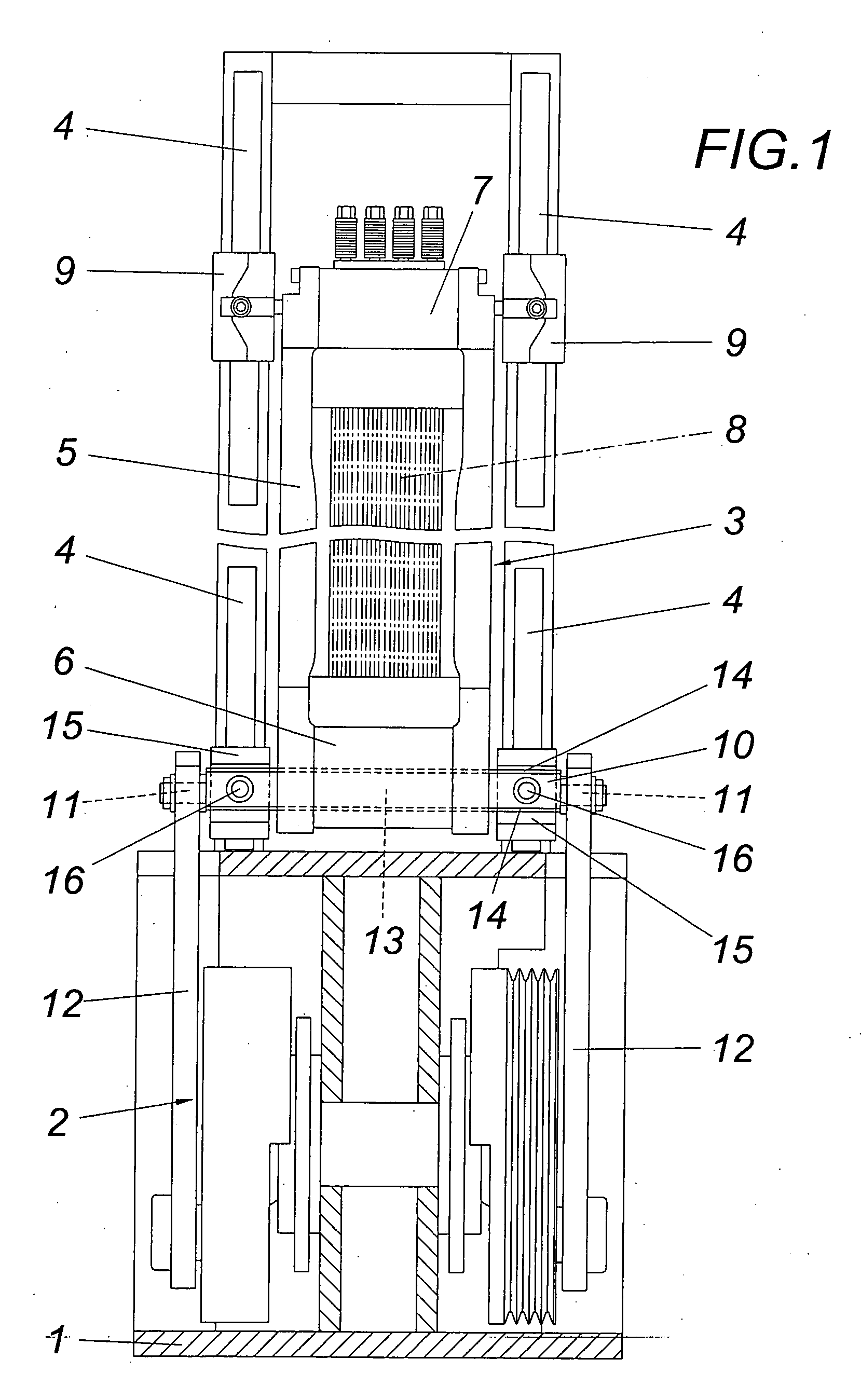
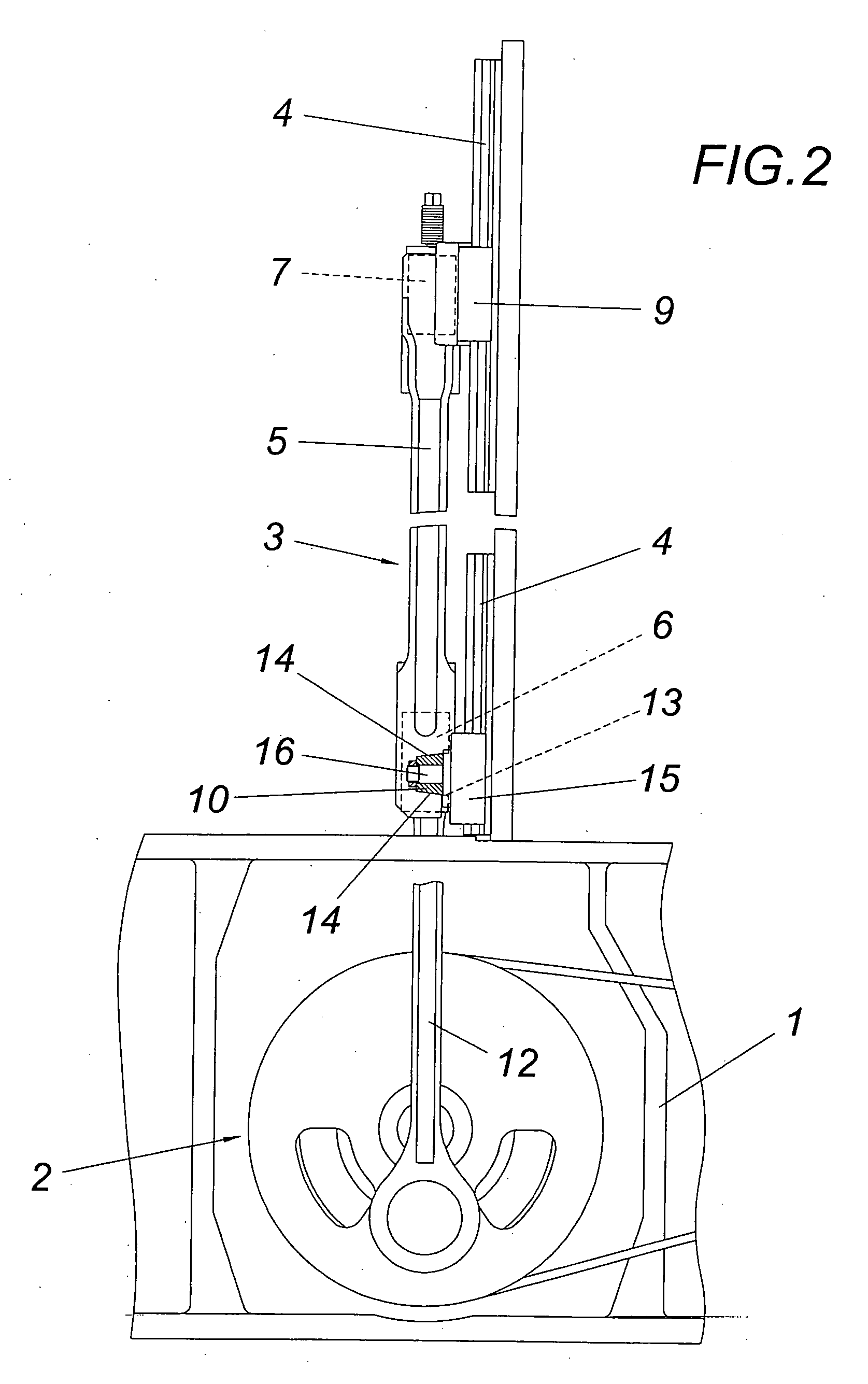
[0011]The illustrated frame saw comprises a frame 1, in which a slider-crank drive 2 for driving a reciprocating frame saw 3 is held. The reciprocating frame saw 3 which is displaceable along its lateral guide rails 4 comprises a sash 5 with two stringers 6, 7 which are connected with each other with long-beams and between which the saw-blades 8 are clamped. Whereas the sash 5 is detachably connected directly with the guide means 9 for the lateral guide rails 4 in the area of the stringer 7 which is remoter to the slider-crank drive 2, the sash 5 rests in the region of the opposite stringer 6 closer to the slider-crank drive 2 on a crossbeam 10 which carries axially protruding link pins 11 for lateral pushrods 12 of the slider-crank drive 2. The crossbeam 10 is held in a receiving groove 13 of the stringer 6. Since the groove walls of the receiving groove 13 converge towards the base of the groove and the crossbeam 10 forms respectively inclined opposite surfaces 14, the crossbeam 1...


PUM


Abstract

A frame saw is described, comprising a reciprocating saw frame (3) which is guided via guide means (9, 15) along lateral guide rails (4) and which comprises a sash (5) with two stringers (6, 7) for clamping parallel saw-blades (8) which cut in only one lifting direction, and a slider-crank drive (2) which is connected with the reciprocating saw frame (3) via lateral pushrods (12) in the area of the stringer (6) closest to the same. In order to provide advantageous constructional conditions it is proposed that the two pushrods (12) of the slider-crank drive (2) act upon a common crossbeam (10) for receiving the sash (5) in the area of the two stringer (6, 7) which is closest to the slider-crank drive (2), that the crossbeam (10) rests with the help of guide means (15) on the lateral guide rails (4), and that the crossbeam (10) is held in a swivelable manner relative to its guide means (15) about an axle (16) perpendicular to the guide rails (4) and the crossbeam (10).

Description

1. FIELD OF THE INVENTION[0001]The invention relates to a frame saw, comprising a reciprocating saw frame which is guided via guide means along lateral guide rails and which comprises a sash with two stringers for clamping parallel saw-blades which cut in only one lifting direction, and a slider-crank drive which is connected with the reciprocating saw frame via lateral pushrods in the area of the stringer closest to the same.2. DESCRIPTION OF THE PRIOR ART[0002]In the case of frame saws with saw-blades clamped in a sash, the reciprocating saw frame which is usually driven via a slider-crank drive is held with the help of slide blocks in lateral guide rails of a frame, with the possibility being provided to link the pushrods of the slider-crank drive to the sash in the area of the stringer closer or remoter relative to the slider-crank drive, between which the saw-blades are clamped. The connection of the pushrods with the closer of said stringers not only provides better accessibil...

Claims


Application Information

Patent Timeline
IPC IPC(8): B26D1/06
CPCB27B3/10Y10T83/6588
Inventor MAYR, REINHOLD
Owner WINTERSTEIGER
Features
  • Generate Ideas
  • Intellectual Property
  • Life Sciences
  • Materials
  • Tech Scout
  • Unparalleled Data Quality
  • Higher Quality Content
  • 60% Fewer Hallucinations
Learn More