Kitchen ventilator system

a ventilator system and kitchen technology, applied in the field of exhaust systems, can solve the problems of large amount of uv radiation, and limited effect of uv radiation on the removal of particulates

Inactive Publication Date: 2008-06-12
PREMARK FEG L L C
View PDF18 Cites 34 Cited by
  • Summary
  • Abstract
  • Description
  • Claims
  • Application Information

AI Technical Summary

Benefits of technology

[0015]Also provided is a kit for retrofitting a ventilator system having a hood portion, a duct portion in fluid communication with the hood portion, and a fan in fluid communication with the duct portion for drawing the cooking exhaust through the hood portion to the duct portion, where the duct portion has an opening in a first side wall. The kit includes at least one ultra-violet lamp disposed in a first surface of a module, where the lamp is configured to be introduced into the opening in the duct portion to extend from a first surface of the module substantially to a second side wall. The module is configured to be fastened to an exterior surface of a first side wall to enclose the opening. An outer housing is configured to be fixed to the exterior surface of the duct portion and is configured for preventing access to the first surface of the module.

Problems solved by technology

Some of these cooking units, such as broilers and fryers, produce considerable quantities of cooking exhaust.
First, the UV lamps emit a large amount of UV radiation, and as such, the UV lamps must be positioned in the ventilator system to avoid user exposure.
It is believed by many skilled in the art that above certain exhaust velocities, the UV radiation has limited effectiveness in removal of particulate.
However, in updating existing ventilation systems, it is difficult to retrofit new UV lamps into the hood plenum, given the limited space constraints inside the hood plenum.

Method used


Image

  • Kitchen ventilator system
  • Kitchen ventilator system
  • Kitchen ventilator system

Examples


Embodiment Construction

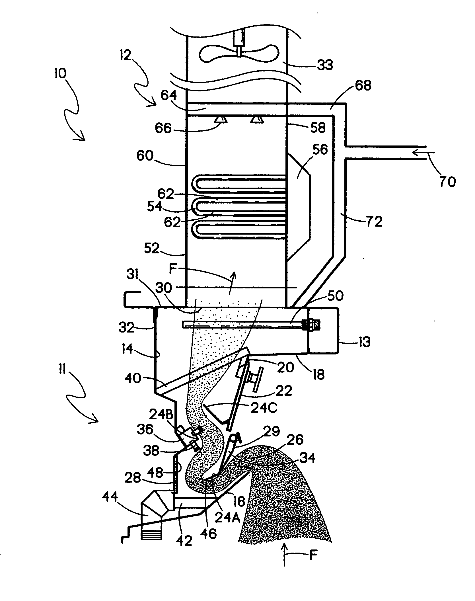
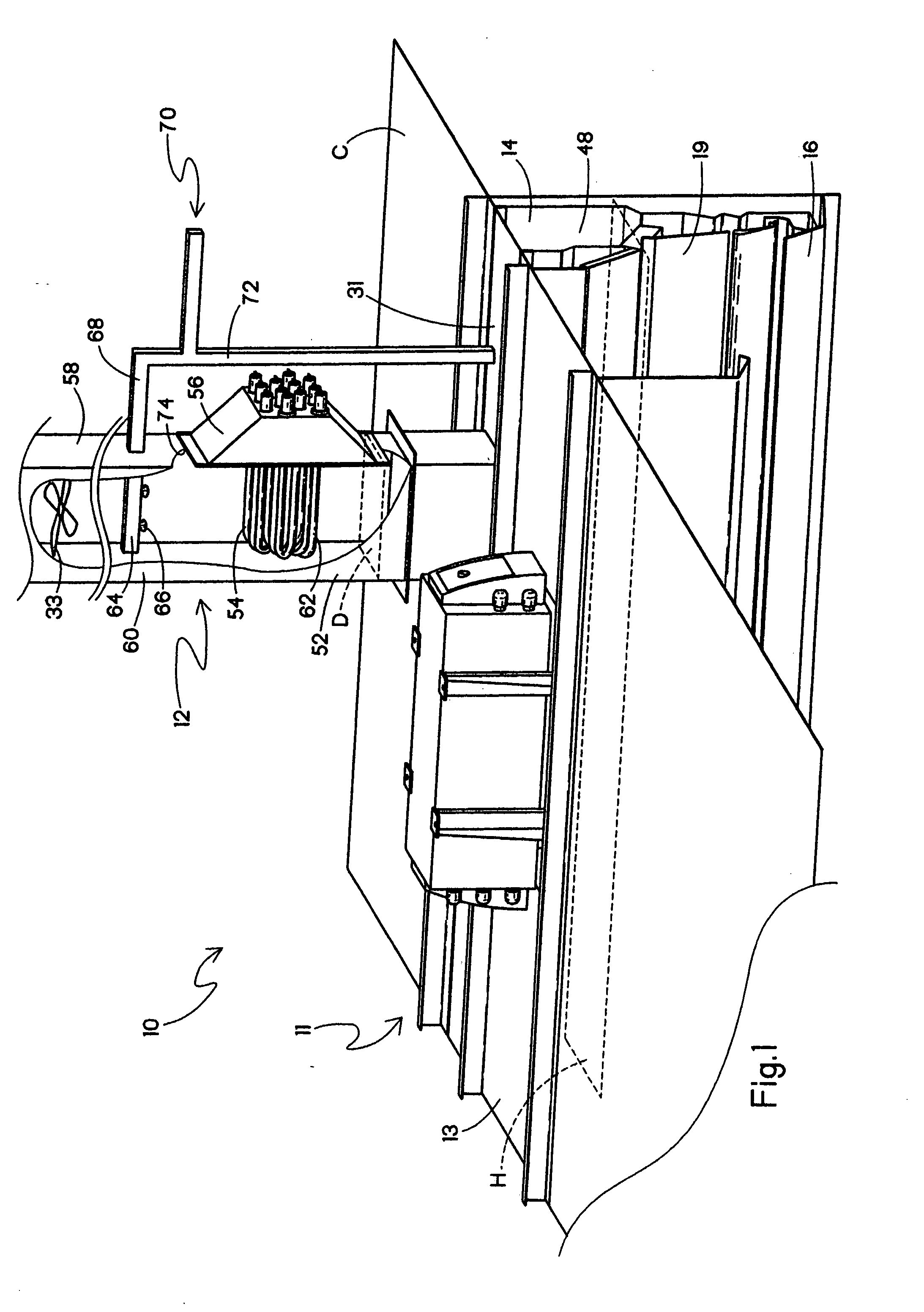
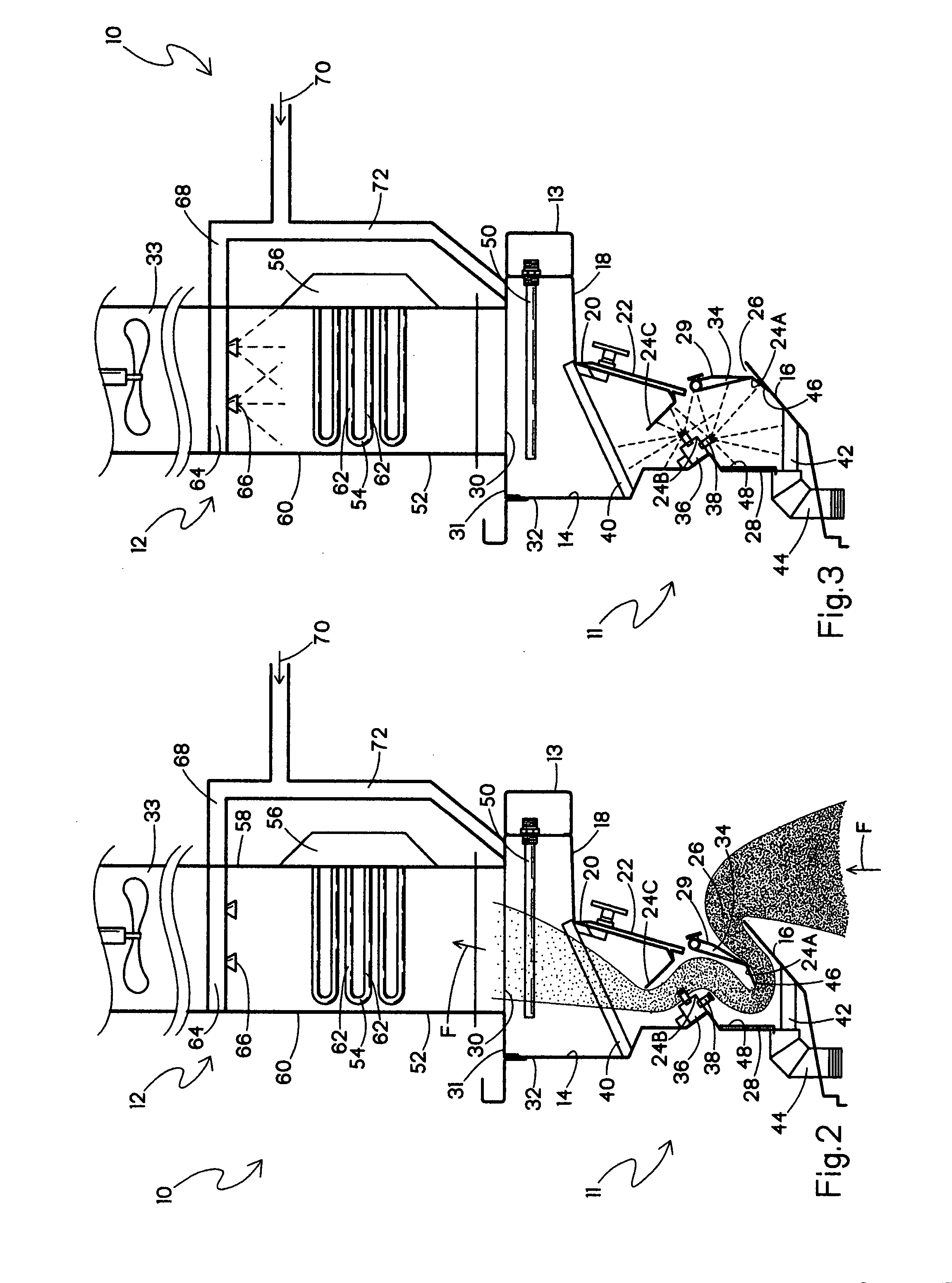
[0021]Referring to FIG. 1, a ventilator assembly 10 is shown in perspective view with part of the right side cut away. The ventilator assembly 10 has a hood portion, indicated generally at 11, which is typically positioned above a large commercial cooking area (not shown) that may include one or more cooking stations such as a griddle, range, fryer, and / or broiler, and is typically mounted to a wall or hung from the ceiling (not shown) over the cooking area. Unless otherwise indicated, the following description is made with reference to the ventilator assembly 10 of FIGS. 1-3, which is of the type that includes an optional water wash system in the hood portion 11. However, it is contemplated that other ventilator assemblies having different hood portions can be used, some lacking such water wash systems.

[0022]A duct portion, indicated generally at 12, is located on the upstream side of the hood portion 11 and is in fluid communication with the hood portion. At least a portion of the...


PUM

PropertyMeasurementUnit
wavelengthaaaaaaaaaa
velocityaaaaaaaaaa
velocityaaaaaaaaaa

Abstract

A ventilator assembly for removing contaminants in cooking exhaust includes a hood portion having a hood plenum, and a duct portion in fluid communication with the hood portion, where the duct portion has an inside cross-sectional area that is less than half of an average inside cross-sectional area of the hoodplenum. A fan is in fluid communication with the duct portion for drawing the cooking exhaust through the hood portion to the duct portion. At least one ultra-violet lamp is disposed in the duct portion, where the ultra-violet radiation from the lamp reacts with the cooking exhaust to generate ozone for oxidizing contaminants in the cooking exhaust.

Description

BACKGROUND OF THE INVENTION[0001]The present invention relates generally to exhaust systems used in commercial kitchens, and more particularly, to kitchen ventilator systems that use ultra-violet light for reacting with air laden with grease, smoke, fumes and moisture rising from various types of cooking units.[0002]Kitchen ventilator systems typically include a hood mounted above the cooking appliances for capturing cooking exhaust. In a commercial kitchen, for example, there are usually a number of cooking units lined up side-by-side in a row. Some of these cooking units, such as broilers and fryers, produce considerable quantities of cooking exhaust. The ventilator hood typically includes an inlet opening above the cooking units for capturing the cooking exhaust.[0003]Conventionally, kitchen ventilator systems incorporate mechanical removal devices, such as extraction baffles, filters and particulate separators disposed in the flow path of the cooking exhaust. The filters and par...

Claims


Application Information

Patent Timeline
Patent Type & Authority Applications(United States)
IPC IPC(8): F24C15/20B65D69/00G21G5/00
CPCF24C15/2057
Inventor ROBISON, RUSSELL
Owner PREMARK FEG L L C
Why Eureka
Try Eureka