Method and apparatus of manufacturing annular concentric stranded bead cord

a technology of concentric strands and bead cords, which is applied in the field of bead cords, can solve the problems of increasing costs, difficulty in automation, and troublesome hand winding of lateral wires, and achieves the effects of preventing lateral deflection, good winding performance, and high speed winding

Inactive Publication Date: 2008-06-12
SUMITOMO ELECTRIC TOCHIGI CO LTD +1
View PDF4 Cites 9 Cited by
  • Summary
  • Abstract
  • Description
  • Claims
  • Application Information

AI Technical Summary

Benefits of technology

[0034]The driving unit includes two pinch rollers. The two pinch rollers rotate the annular core in the peripheral direction in a stable state without any slipping. A clamp unit is provided at a lateral-wire supply side, and performs positioning of the winding point while preventing lateral deflection as a result of holding the entire periphery at the winding point of the lateral wire and the annular core.
[0035]Accordingly, according to the invention, it is possible to provide a method of manufacturing an annular concentric stranded bead cord, which makes it possible to perform winding at a high speed and to provide good winding performance because a reel is made to undergo a pendulum swinging movement, and which make it possible to achieve good formability of the cord without a disturbance in the arrangement state of a lateral wire as a result of stabilizing the rotation of an annular core in a peripheral direction.

Problems solved by technology

Therefore, it is difficult to achieve automation, and there are many factors that increase costs.
In addition, when the coil diameter of the lateral wire, which is wound upon the annular core, is large, it is troublesome to wind the lateral wire by hand.
Further, since the lateral wire is previously modified, resistance is increased when the lateral wire is drawn out, thereby causing winding problems.
Even with a small tension, the annular core tends to become deformed, thereby adversely affecting windability.
In addition, there are many unnecessary movements, and the apparatus, itself, becomes massive.
Therefore, as the difference between the winding deviation angle βS and the twist angle β becomes large as mentioned above, the state of arrangement of the lateral wire 2 that is being continuingly wound tends to become disturbed, thereby resulting in poor cord formability.
Further, as regards the method disclosed in Japanese Unexamined Patent Application Publication No. 2001-47169 in which the reel 3 revolves to the inner side and the outer side of the annular core 1, since the reel 3 moves along a circular path, its movement is redundant, thereby requiring a long period of time until the winding ends.
Therefore, the annular core 1 tends to meander, resulting in poor windability.
Therefore, similarly to the case disclosed in Japanese Unexamined Patent Application Publication No. 2001-47169, the winding deviation angle βS varies considerably, thereby resulting in unstable windability.
Unless the movement of the annular core, which becomes the base during the winding, is maximally limited, the windability tends to become unstable.
In particular, since the annular core is placed in a gravitational direction and is moved vertically with respect to the gravitational direction, and the reel, upon which the lateral wire is wound, is continuously moved, the windability is poor.
Consequently, it is difficult to arrange the lateral wire 2, as a result of which the arrangement of the lateral wire 2 tends to be disturbed.
Therefore, the entire apparatus becomes large, the rotation of the annular core 1 in the peripheral direction becomes unstable, and the arrangement of the lateral wire tends to become disturbed.

Method used


Image

  • Method and apparatus of manufacturing annular concentric stranded bead cord
  • Method and apparatus of manufacturing annular concentric stranded bead cord
  • Method and apparatus of manufacturing annular concentric stranded bead cord

Examples


Embodiment Construction

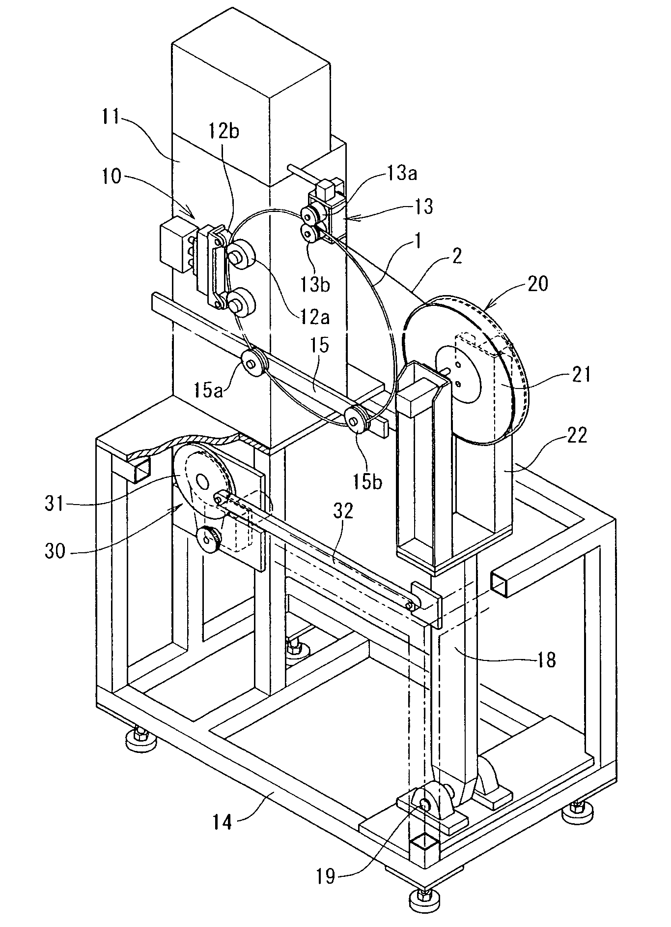
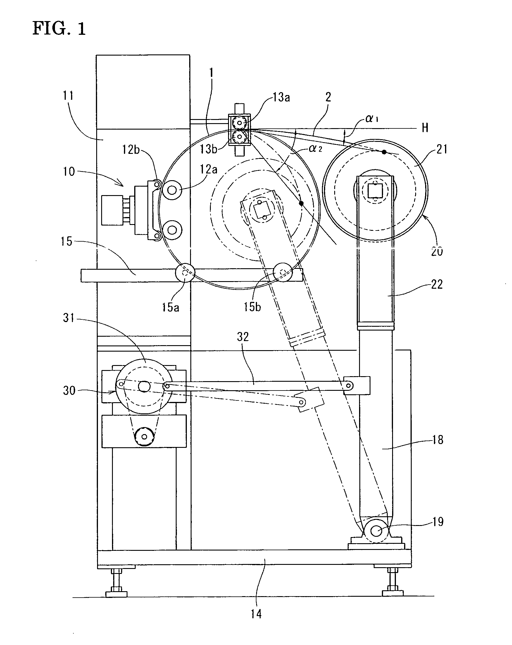
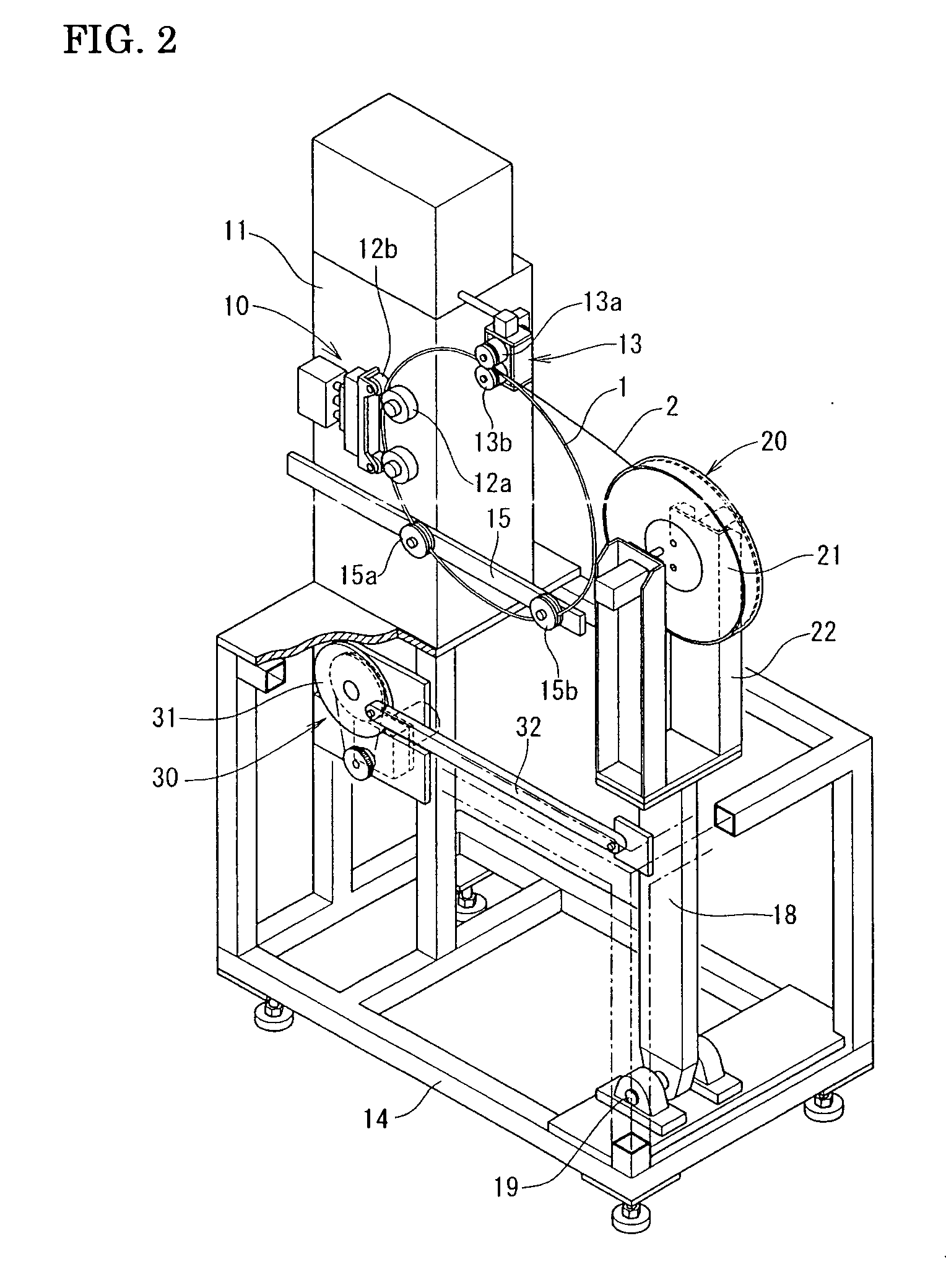
[0051]An apparatus of manufacturing an annular concentric stranded bead cord according to an embodiment of the present invention will be described with reference to FIGS. 1 to 8.

[0052]The manufacturing apparatus includes a driving unit 10 and a supply unit 20. The driving unit 10 rotates an annular core 1 at its fixed position in a peripheral direction. The supply unit 20 supplies a lateral wire 2, wound upon a reel 21, to a winding portion of the annular core 1.

[0053]The driving unit 10 includes two pinch rollers 12a and 12b, connected to a drive motor, for rotating the annular core 1 in the peripheral direction in a vertical plane. The pinch rollers 12a and 12b are set at a support 11 on a table 14.

[0054]A clamp unit 13, which surrounds the annular core 1, is provided at the support 11 so as to be situated at a supply side of the lateral wire 2 situated in a direction opposite to the direction of rotation of the annular core 1. The clamp unit 13 includes two rollers, rollers 13a a...


PUM

PropertyMeasurementUnit
winding deviation angle βSaaaaaaaaaa

Abstract

A method of manufacturing an annular concentric stranded bead cord, wherein, while rotating an annular core at a fixed position in a peripheral direction, a reel, upon which a lateral wire is wound, repeatedly performs a pendulum swinging movement and a perpendicular movement with respect to the annular core, thereby spirally winding the lateral wire upon the annular core to form a sheath layer. When forming the sheath layer, a fulcrum of the pendulum swinging movement of the reel is determined so that, with reference to a tangential line of a circle of the annular core passing through a winding point where the lateral wire is wound upon the annular core, the lateral wire is wound upon the winding point of the annular core within 15 degrees at a position above the tangential line and within a range of 55 degrees at a position below the tangential line.

Description

BACKGROUND OF THE INVENTION[0001]1. Field of the Invention[0002]The present invention relates to a bead cord which is embedded in a bead portion of a pneumatic tire. More particularly, the present invention relates to a method and an apparatus of manufacturing an annular concentric stranded bead cord having one sheath layer or a plurality of sheath layers formed by continuingly spirally winding a lateral wire along an annular core.[0003]2. Description of the Related Art[0004]An annular concentric stranded bead cord is used in tires of various types of vehicles.[0005]As shown in FIGS. 9A and 9B, an annular concentric stranded bead cord includes a sheath layer of lateral wire 2 provided upon an annular core 1. It is manufactured by continuingly spirally winding the lateral wire 2 along the annular core 1 as a result of passing the lateral wire 2 to the inner side of a ring of the annular core 1 from the outer side of the annular core 1, and, then, passing them again to the inner side ...

Claims


Application Information

Patent Timeline
Patent Type & Authority Applications(United States)
IPC IPC(8): B29D30/48
CPCB29D30/48C21D8/06D02G3/48
Inventor SANO, YUICHIWAKAHARA, HITOSHIOKAMOTO, KENICHI
Owner SUMITOMO ELECTRIC TOCHIGI CO LTD
Why Eureka
Try Eureka