Medical Stapler

a stapler and medical technology, applied in the field of medical staplers, can solve the problems of difficult to precisely read the number of staples, complicated structure and so not practical, and it is not possible to determine whether or not sufficient sewing can be accomplished using the same stapler. , to achieve the effect of simple structur

Inactive Publication Date: 2008-06-12
MAX CO LTD
View PDF11 Cites 936 Cited by
  • Summary
  • Abstract
  • Description
  • Claims
  • Application Information

AI Technical Summary

Benefits of technology

[0012]One or more embodiments of the present invention provide a medical stapler capable of knowing the number

Problems solved by technology

So it is difficult to read the number of staples exactly.
The document stapler disclosed in JP-U-60-178585 is complicate in structure and so not practical.
Further, where there are plural wounds, when another wound is sewed u

Method used


Image

  • Medical Stapler
  • Medical Stapler
  • Medical Stapler

Examples


embodiment 1

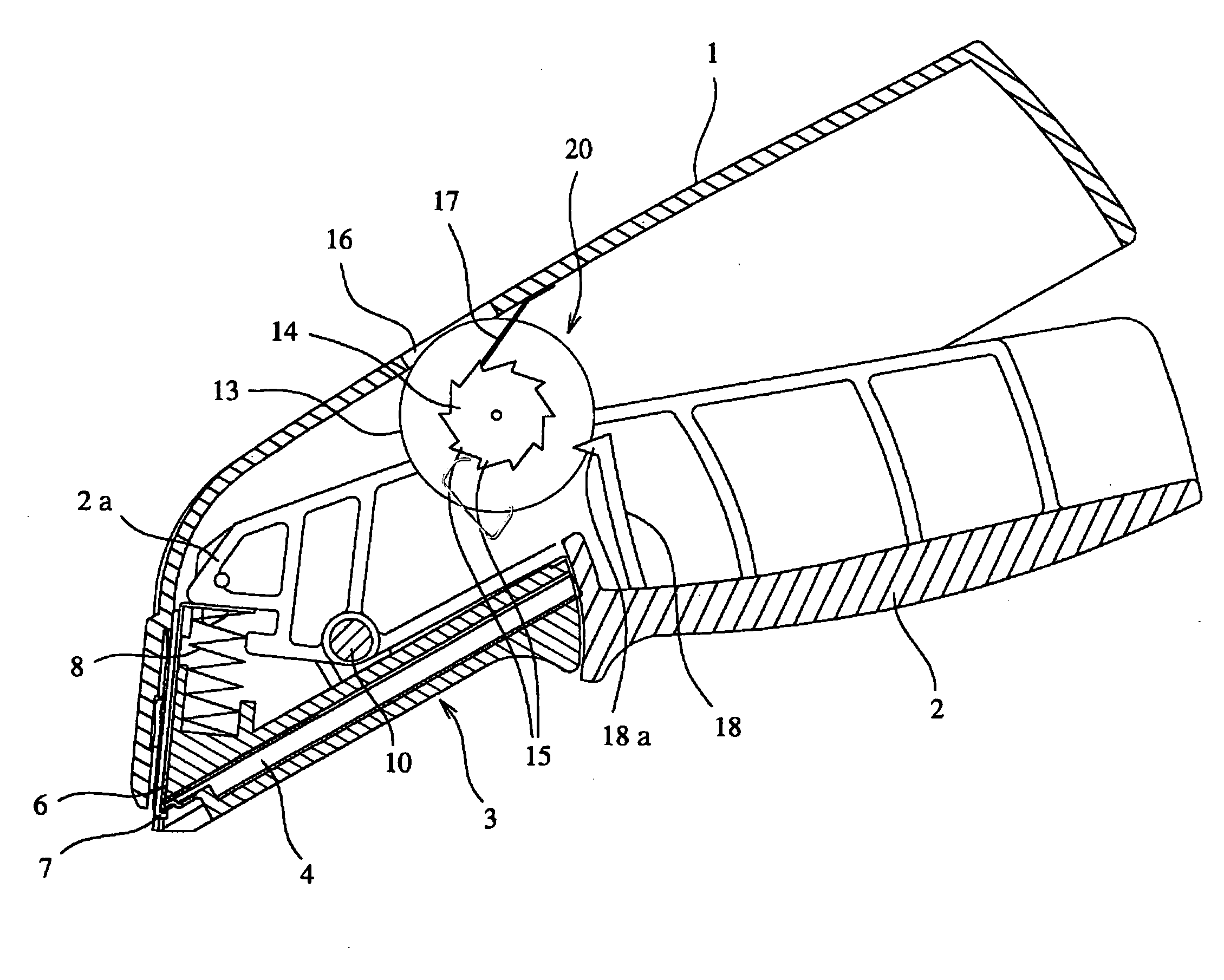
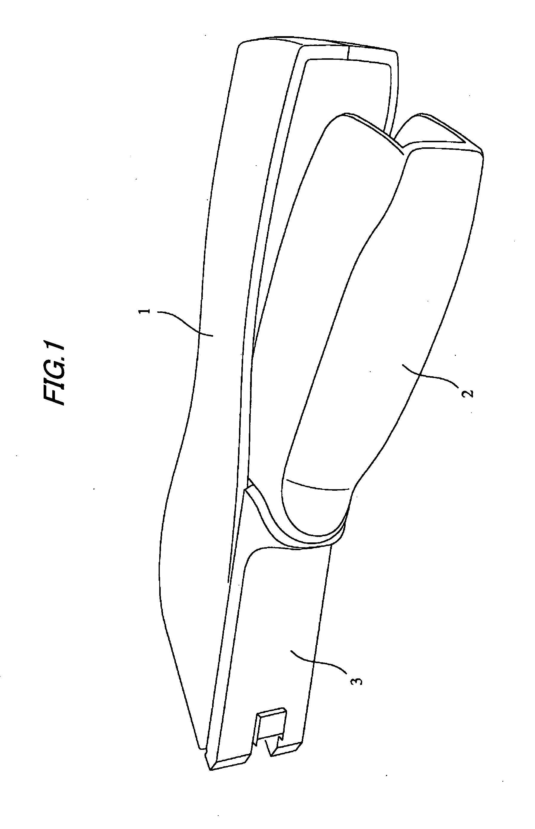
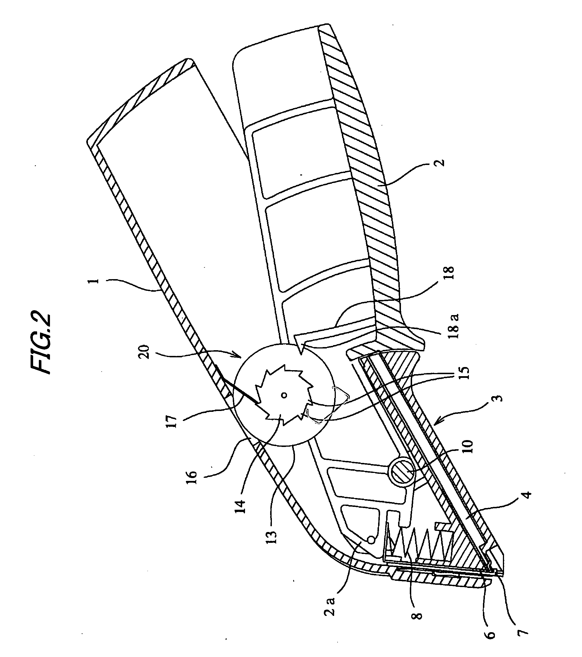
[0038]FIG. 1 is a perspective view of an embodiment of the present invention. FIG. 2 is an enlarged longitudinal sectional view of the above stapler. FIG. 3 is a longitudinal sectional view of the front part of the above stapler. In the drawings, reference numeral 1 denotes a stapler body, and 2 denotes a manipulating lever.

[0039]At the internal tip of the stapler body 1, a staple feeding path 4 and a driving mechanism A are provided. Above a driving section 5 formed at the front end of the staple feeding path 4, a driver plate 6 is arranged vertically slidably. Below the driving section 5, an anvil 7 is formed. The driver plate 6 is urged by a spring 8 so that it is always located at an initial position. Incidentally, as seen from FIG. 6(a), the lower end of the driver plate 6 is formed in an inverted concave shape having projecting pieces 6a formed on both sides. The staples 9 within the staple feeding path 4 are can be always supplied to the driving section 5 by a pusher 11 and a...

embodiment 2

[0048]FIGS. 9 and 10 show another embodiment. In this embodiment, the latchet 14 is arranged on the rear side of the stapler body 1 and the actuating piece 18 is also arranged on the rear side of the manipulating lever 2. Further, the detent 17 is provided on the back side of the upper face of the stapler body 1. The transparent window 16 is formed on the rear side of the stapler body 1.

[0049]In accordance with the above configuration also, whenever the manipulating lever 2 is pulled up, one of the teeth 15 of the latchet 14 is rotated. Correspondingly, the numeral counted up by one is indicated on the indicator disc 13. By seeing this numeral through the transparent window 16, the number of staples 9 already used for sewing-up can be confirmed.

embodiment 3

[0050]FIG. 11 shows a mechanism for electronically counting the number of staples 9 in which a sensor 19 for detecting the staple 9 is arranged behind the anvil 7 in the driving section of the stapler body 1 and the staple 9 exhausted after having been driven and bent is detected for counting. The counted result may be indicated on the indicator disc 13.

[0051]The present invention has been explained in detail and referring to the specific embodiment. However, it is apparent to those skilled in the art that the present invention can be changed or modified in various manners without departing from the spirit and scope of the invention.

[0052]This application is based on Japanese Patent Application (Patent Application No. 2004-268883) filed on Sep. 15, 2004, and the contents of which are incorporated herein by reference.


PUM


Abstract

A medical stapler is provided with a sterilized cartridge removably attached to a stapler body 1 and accommodating a predetermined number of staples 9, a driving mechanism for driving a staple 9 supplied to a driving section at the tip of the cartridge, a manipulating lever 2 for actuating the driving mechanism and a counter device 20. The counter device 20 counts the number of staples 9 driven from the driving mechanism and indicates the counted result.

Description

TECHNICAL FIELD[0001]The present invention relates to a medical stapler employed to sew up a wound in a surgical operation.BACKGROUND ART[0002]Generally, after a tissue of a living body has been incised in a surgical operation, a wound is sewed up using a sewing thread. For the reasons that an operation trace is not conspicuous and the healing is rapid, a system of sewing up using a staple is also adopted.[0003]A medical stapler is provided with a stapler body including a driving mechanism and a manipulating lever for actuating the driving mechanism. By rotating the manipulating lever, staples are pushed out one by one and the staple is put into skin while it is being bent. Thus, after the skin has been sewed up, the staple is removed from the stapler body.[0004]Meanwhile, in the medical stapler, the staple itself as well as the stapler body must be sterilized previously. Further, in a scene of medical treatment, in order to prevent such a medical accident that the staple is erroneo...

Claims


Application Information

Patent Timeline
IPC IPC(8): A61B17/10
CPCA61B17/0684A61B2019/4836A61B2019/4815A61B2090/0803A61B2090/0807
Inventor HIRANUMA, TOSHIOHASHIMOTO, MASAHIKOYAMAGUCHI, SHIGENORI
Owner MAX CO LTD
Why Eureka
Try Eureka