Filter circuit arrangement

a filter circuit and filter circuit technology, applied in pulse manipulation, pulse technique, continuous tuning, etc., can solve the problems of limited phase accumulator output resolution, unwanted ancillary emissions, and disruption of appertaining applications, so as to achieve a wide range of capture and not impair transmission behavior

Inactive Publication Date: 2008-06-12
SIEMENS HEALTHCARE GMBH
View PDF7 Cites 38 Cited by
  • Summary
  • Abstract
  • Description
  • Claims
  • Application Information

AI Technical Summary

Benefits of technology

[0012]An object of the present invention is to improve a filter of the aforementioned type so that the capture range is enlarged, while not impairing the transmission behavior (advantageously the high selectivity of the filter) by the expansion of the capture range.

Problems solved by technology

For technical reasons, however, the resolution of the phase accumulator output is limited to a practical data word width in available DDS modules.
Such spurious signals can lead to disruptions in the appertaining application in which the DDS system is used as a local oscillator.
For example, if (as an oscillator) a frequency mixer of a transmitter is controlled with a DDS signal, unwanted ancillary emissions can occur.
Given a use of DDS signals as local oscillators in a medical imaging method, this can also lead to artifacts, for example.
Spurious signals lying within the DDS tuning range pass the filter unattenuated.
However, the output signal is charged with additional noise due to the mixing process.
The regulation can therefore not tune or “capture” or “lock”.
The capture range can in fact be enlarged by increasing the bandwidth of the filter 5 used in the filter circuit is increased, but this has the disadvantage that the filter circuit arrangement no longer filters as well, and also that spurious signals lying further removed from the center frequency can pass through the filter.
For this reason the filter circuit arrangement is not suitable for applications in which a large selection on the one hand and a large capture range on the other hand are required.
The design of a circuit arrangement for generation of a local oscillator signal adjustable in a wider frequency range (for example with a DDS as an oscillator) is thus not possible with this filter circuit arrangement.
In this design the problem also exists that, given an input signal whose frequency lies far outside the current set (via the variable center frequency) through-pass band, the amplitude of the fed-back signal is not sufficient in order to let the loop lock.
This particular type of capture range expansion is limited, however, to the specific application with N-path filters (since the transmission phase of the detour path for the locking process of the filter hereby remains unconsidered) and is not suitable for a usage with classical LC filters.
However, N-path filters exhibit known, serious disadvantages relative to classical LC filters.
The design is thus not suitable for high-frequency bandpass filters.

Method used


Image

  • Filter circuit arrangement
  • Filter circuit arrangement
  • Filter circuit arrangement

Examples


Embodiment Construction

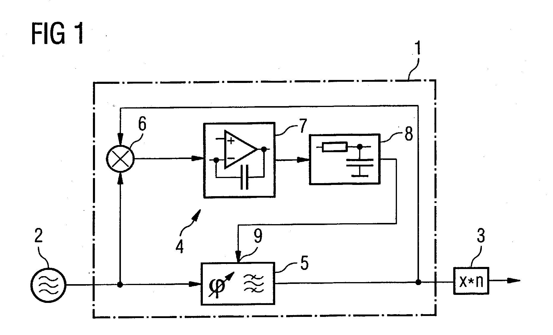
[0037]The basic principle of a circuit arrangement for generation of a local oscillator with an oscillation generator and a downstream filter circuit arrangement with a phase regulation loop was already explained above using FIG. 1. The phase regulation loop has a phase detector that compares a desired signal with a feedback signal and generates a control signal for the tunable filter. For further explanations in this regard, DE 10 2005 024 624 is referenced.

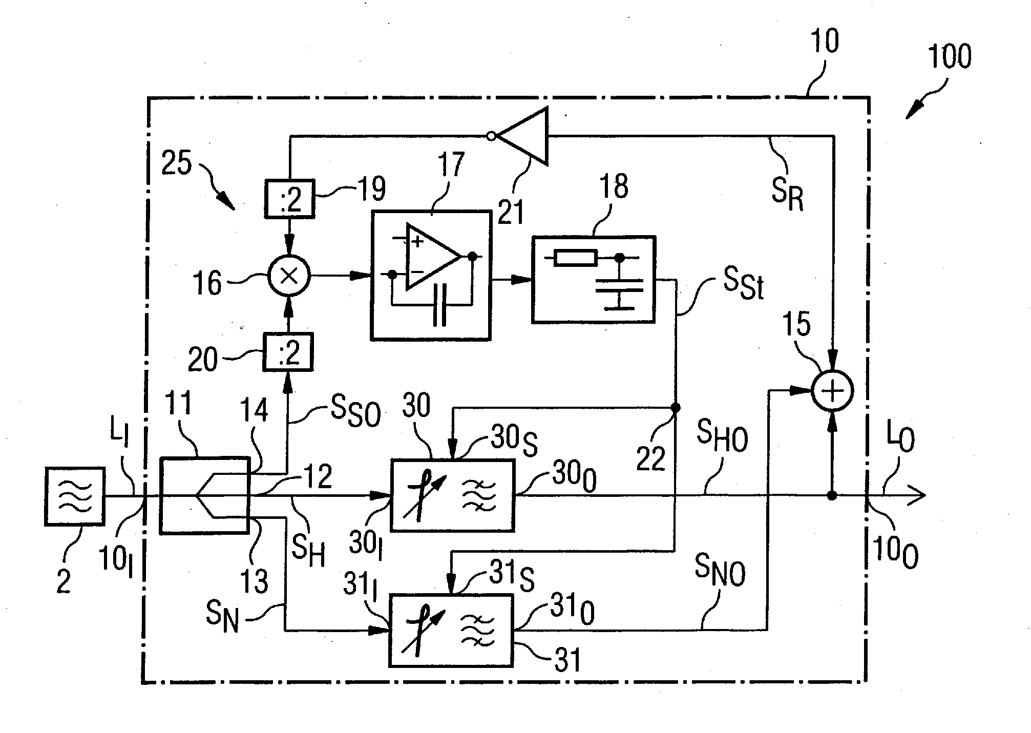
[0038]This principle is expanded by a side branch in the inventive design of such a circuit arrangement 100. This means that a feedback signal is now generated that is also influenced by an output signal of this side branch.

[0039]In the exemplary embodiment shown in FIG. 2 the local oscillator signal LI to be filtered (which is generated by an oscillator 2, here a DDS oscillator 2) is provided at an input 10I of the filter circuit arrangement 10 for this. A decoupled power splitter 11 with three outputs 12, 13, 14 is located on ...


PUM


Abstract

A filter circuit arrangement for filtering of a radio-frequency signal has a first tunable filter and a phase regulation loop in order to hold the first tunable filter to a transmission phase constant relative to the frequency of the radio-frequency signal. The filter circuit arrangement has a second tunable filter arranged parallel to the first tunable filter in the phase regulation loop. The first tunable filter and the second tunable filter exhibit different attenuation characteristics and are fashioned and connected within the phase regulation loop so that: a capture range of the filter circuit arrangement, in which a tuning of the phase regulation loop to a radio-frequency signal to be filtered is possible is dominated by the attenuation characteristic of the second tunable filter, and so that the transmission behavior of the filter circuit arrangement in operation is dominated by the attenuation characteristic of the first tunable filter, given a tuned phase regulation loop. A circuit arrangement for generation of a local oscillator signal has an oscillation generator and a filter circuit arrangement as described above arranged downstream of the oscillation generator.

Description

BACKGROUND OF THE INVENTION[0001]1. Field of the Invention[0002]The present invention concerns a filter circuit arrangement for filtering a radio-frequency signal with a tunable circuit and a phase regulation loop in order to hold the tunable filter to a constant transmission phase relative to the frequency of the radio-frequency signal.[0003]2. Description of the Prior Art[0004]In many technical fields, high-quality radio-frequency signal sources, whose signal frequencies can be adjusted in small steps (i.e. virtually continuously), are necessary in a number of applications. A typical example is local oscillators in receivers and transmitters in communication technology. For example, specific lower and upper frequency limits, an optimally low frequency step width and an optimally high step speed with simultaneously high adjustment precision and constancy of the set frequency, are among the requirements for such a radio-frequency signal source. Moreover, normally a minimal phase noi...

Claims


Application Information

Patent Timeline
Patent Type & Authority Applications(United States)
IPC IPC(8): H03L7/081H03K5/00H03L7/08H03L7/06
CPCH03J3/185H03H11/1291
Inventor BOLLENBECK, JANOPPELT, RALPH
Owner SIEMENS HEALTHCARE GMBH
Why Eureka
Try Eureka