Beam Separation Apparatus for Monostatic Lidars

a monostatic lidar and beam separation technology, applied in instruments, distance measurement, climate sustainability, etc., can solve problems such as power loss

Inactive Publication Date: 2008-06-12
SELENIA SPAZIO SPA
View PDF0 Cites 32 Cited by
  • Summary
  • Abstract
  • Description
  • Claims
  • Application Information

AI Technical Summary

Benefits of technology

[0018]A further advantage of this invention is that substantially no fraction of the backscattered light (coming from the atmosphere or from the optical elements after the second polarizing beam splitters) reaches the laser source. The apparatus disclosed here is also, by its nature, an optical isolator, so that no additional devices of this kind are necessary to avoid light feedbacks into the laser (these feedbacks degrade the frequency stability of the source).
[0019]Finally, this apparatus is simple and only made by solid-state elements. This makes it suitable to space applications, carried on board a spacecraft.

Problems solved by technology

The only power losses are due to the limited intrinsic transmissivity of the various optical elements.

Method used


Image

  • Beam Separation Apparatus for Monostatic Lidars
  • Beam Separation Apparatus for Monostatic Lidars
  • Beam Separation Apparatus for Monostatic Lidars

Examples


Embodiment Construction

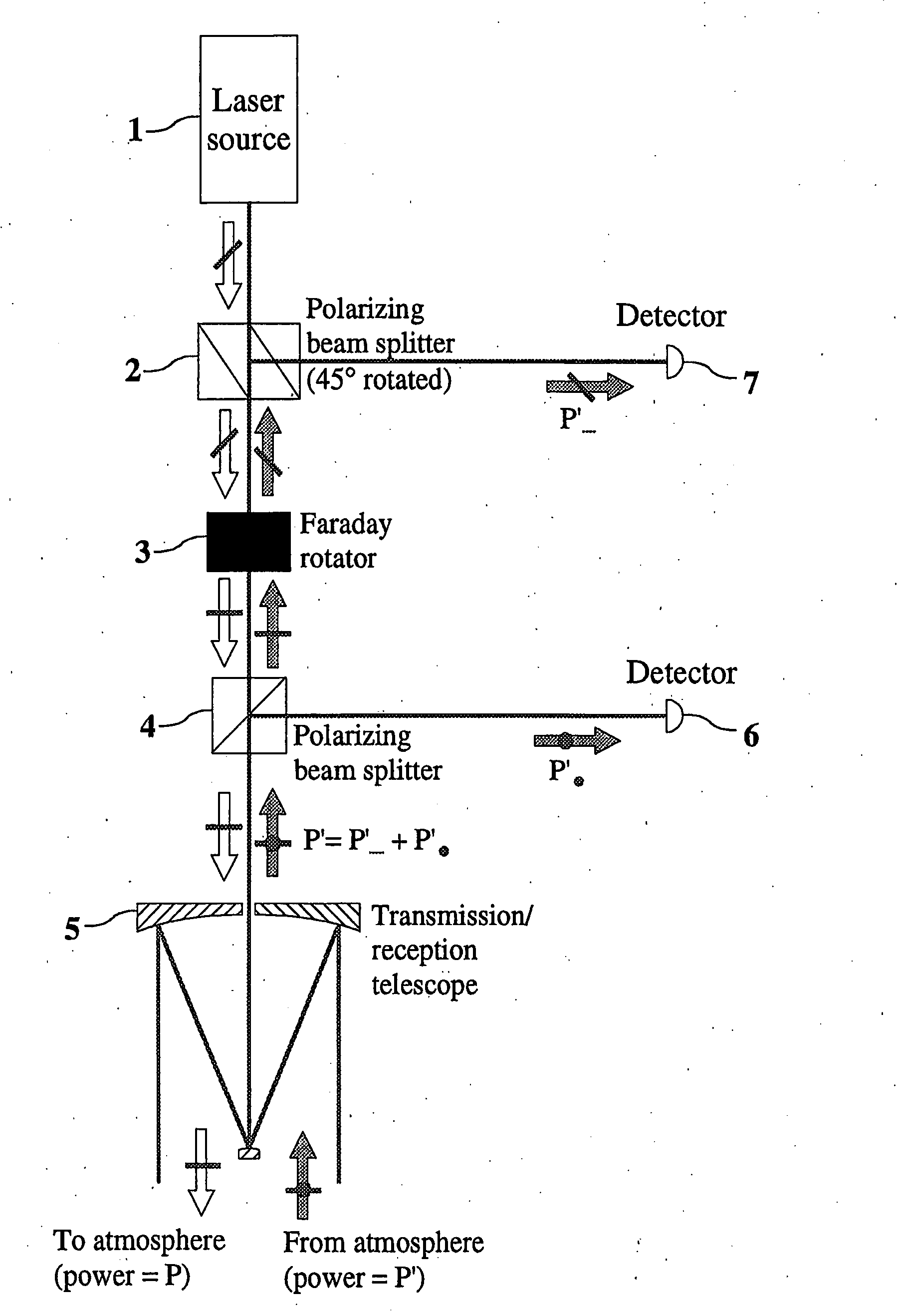
[0026]FIG. 4 shows the scheme of a monostatic LIDAR including the beam separation system, according to the present invention. The laser source 1 emits a beam of power P, with a linear polarization lying in a plane rotated through an angle of 45° with respect to the plane of the optical bench (assumed as reference plane). The beam encounters the first polarizing beam splitter 2, also rotated through an angle of 45° with respect to the optical bench, so that the incoming polarized light is substantially all transmitted. The correct orientation of the polarizing beam splitter 2 is shown in FIG. 5. The Faraday rotator 3 is placed after the polarizing beam splitter 2. It rotates the laser beam polarization plane through an angle of 45° in counter clockwise direction so as to make it parallel to the optical bench plane (“horizontal” polarization). The third polarizing beam splitter 4 is placed after the Faraday rotator 3 with its faces parallel to the optical bench, oriented so that the h...


PUM


Abstract

Monostatic LIDARs use the same telescope to send the laser beam in atmosphere and to collect the backscattered echo. An important element of monostatic LIDARs is the optical separator between the emission and reception paths of the laser beam. By using a system made by a Faraday rotator in combination with two polarizing beam splitters suitably oriented, it is possible to achieve this separation with minimum losses with respect to prior systems using semi-reflective plates and/or polarizing beam splitters in conjunction with quarter-wave plates. The effectiveness of this system does not rely on the maintenance of the polarization status of the laser beam when backscattered by the atmosphere molecules and particles, neither on the reduction of the received laser power relatively to the transmitted one. The system is simple, compact, and can work at several wavelengths of the laser source.

Description

REFERENCES CITEDU.S. Patent Documents[0001]U.S. Pat. No. 5,847,815 Aug. 8, 1998 Albouy et al.Other Publications[0002]EarthCARE—Earth Clouds, Aerosols and Radiation Explorer, European Space Agency Report SP-1257(1), September 2001.BACKGROUND OF THE INVENTION[0003]1. Field of the Invention[0004]The present invention relates to monostatic LIDAR (LIght Detection And Ranging) instruments. The LIDAR is an instrument that makes it possible to determine some properties of the atmosphere (aerosol and water vapour contents, wind velocity, temperature, cloud heights, etc.) by transmitting a laser beam in the atmosphere and analyzing (measuring the time of flight, the Doppler shift, the spectral distribution, etc.) that part of the light which is back scattered towards the instrument.[0005]In a monostatic LIDAR the same telescope is used to send the laser beam in atmosphere and to collect the backscattered echo. An important element of the monostatic LIDAR is the optical system separating the e...

Claims


Application Information

Patent Timeline
Patent Type & Authority Applications(United States)
IPC IPC(8): G01S7/481G01S17/95
CPCG01S17/95G01S7/4811Y02A90/10
Inventor CESARE, STEFANO
Owner SELENIA SPAZIO SPA
Why Eureka
Try Eureka